28
Section 4 Model 764 Differential Pressure Transmitter
hub in place with a wrench, carefully thread the QDC into the transmitter
conduit hub and tighten to 50 to 75 ft-lb. Take care to protect the QDC
leads during the connector tightening process.
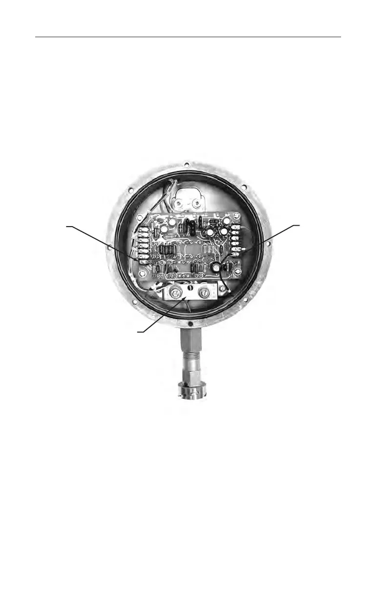
4. Connect the red and black signal leads to the transmitter circuit board
(TB 1-7 & TB 2-6) as shown in Figure 4.2.
5. Install/tighten the two base screws on the Zero and Span mounting
bracket.
6. Install the transmitter cover (see procedure on page 25).
Zero and span bracket
TB1-7
(red)
TB2-6
(black)
Figure 4.2—Wiring for EGS quick disconnect connector assembly