24
Section 4 Model 764 Differential Pressure Transmitter
socket or a wrench.
IMPORTANT: If there are no calibration access plugs in the cover, the cover must be
removed to adjust calibration (see Transmitter Cover Removal, page
25).
3. Connect the electrical readout device to the transmitter as shown in Fig-
ure 3.3, page 20, for either current or voltage readout. If the transmitter
is equipped with an EGS Quick Disconnect connector assembly, secure
the two mating connectors with the bayonet ring (Figure 4.1, page 26).
4. With minimum calibration pressure applied, compare the output signal to
the recommended value in Table 4.2, and adjust the zero control potenti-
ometer in the compensating direction as required.
5. Repeat step 4 at eight or more checkpoints (pressures) from minimum to
full-scale calibrated pressure and back to minimum pressure. Compare
each output to the Table 4.2 specications and adjust the zero and span
potentiometers as required.
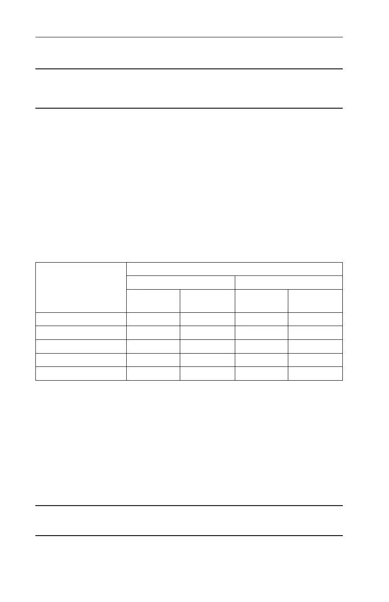
Table 4.2—Calibration Checkpoints
Applied Calibration
Pressure Checkpoint
(% of Full Scale)
Output*
4-20 mA Transmitter** 10-50 mA Transmitter***
Current
(±0.08 mA)
Voltage
(±0.04 Vdc)
Current
(±0.2 mA)
Voltage
(±0.04 Vdc)
0% 4 mA 2 Vdc 10 mA 2 Vdc
25% 8 mA 4 Vdc 20 mA 4 Vdc
50% 12 mA 6 Vdc 30 mA 6 Vdc
75% 16 mA 8 Vdc 40 mA 8 Vdc
100% 20 mA 10 Vdc 50 mA 10 Vdc
*This value includes the eects of conformance (non-linearity), deadband, hysteresis, and repeatability.
**This value was obtained using a 500-Ohm load resistor.
***This value was obtained using a 200-Ohm load resistor.
6. Replace the calibration access plugs as follows (or if the cover has no
calibration access plugs and was removed, see page 25 for instructions
on replacing the cover).
a. Replacement of the calibration plug O-rings is recommended (coat
with a small amount of silicone grease).
b. Install the calibration plugs.
c. Tighten the plugs until they are snug (no applicable torque values).
IMPORTANT: The plugs should be tightened only to prevent loosening due to vibration
without interfering with zero and span potentiometer adjustments.