20
Section 3 Model 764 Differential Pressure Transmitter
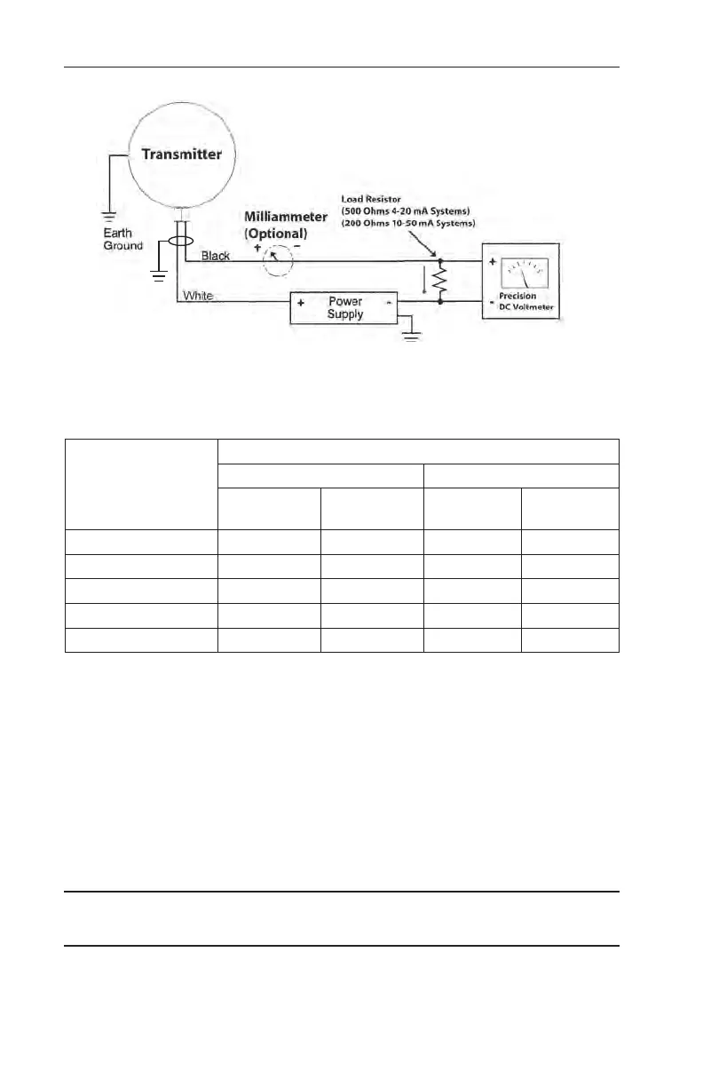
Figure 3.3—Electrical connections for calibration
Table 3.1—Calibration Checkpoints
Applied Calibration
Pressure Check-
point (% of Full
Scale)
Output*
4-20 mA Transmitter** 10-50 mA Transmitter***
Current
(±0.08 mA)
Voltage
(±0.04 Vdc
Current
(±0.2 mA)
Voltage
(±0.04 Vdc)
0% 4 mA 2 Vdc 10 mA 2 Vdc
25% 8 mA 4 Vdc 20 mA 4 Vdc
50% 12 mA 6 Vdc 30 mA 6 Vdc
75% 16 mA 8 Vdc 40 mA 8 Vdc
100% 20 mA 10 Vdc 50 mA 10 Vdc
*This value includes the eects of conformance (non-linearity), deadband, hysteresis, and repeatability.
**This value was obtained using a 500-Ohm load resistor.
***This value was obtained using a 200-Ohm load resistor.
7. Replace the calibration access plugs as follows (or if the cover has no
calibration access plugs and was removed, see page 25 for instructions
on replacing the cover).
a. Replacement of the calibration plug O-rings is recommended (coat
with a small amount of silicone grease).
b. Install the calibration plugs.
c. Tighten the plugs until they are snug (no applicable torque values).
IMPORTANT: The plugs should be tightened only to prevent loosening due to vibration
without interfering with zero and span potentiometer adjustments.