15
Model 752 and 752A Differential Pressure Transmitter Section 3
Perform the following steps to complete eld wiring.
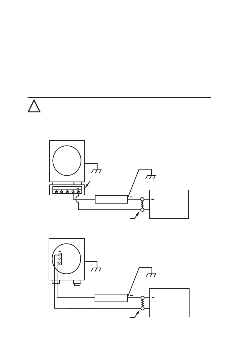
1. Connect the power supply and the receiver to the transmitter as shown in
Figures 3.1 and 3.2.
2. Determine the total loop resistance required for the installation, using
Figure 3.3, page 16, for reference. The total loop resistance must be less
than the maximum calculated value. Table 3.1, page 16, provides loop
resistance values for various cable wire sizes.
3. Install a load resistor sized for the application.
!
WARNING: Failure to properly calculate power supply DC output voltage
may result in inaccurate transmitter readings, possibly leading to safety
system performance degradation during design basis events. To avoid
equipment inaccuracy hazards, follow the examples and tables in this
section for determining the proper power supply DC output voltage.
+
GND
Receiver
Power Supply
+
+
Junction Box
Load Resistor
Model
752/752A
Figure 3.1—Typical eld wiring connections for Model 752 and 752A with junction box
Receiver
Power Supply
+
+
Load Resistor
Model
752 /
752A
+
Figure 3.2—Typical eld wiring connections for Model 752 and 752A without junction
box