6
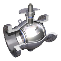
9 Or in a vertical run.
Depending on the valve
and actuator combination,
bracing may be needed to
support the actuator.
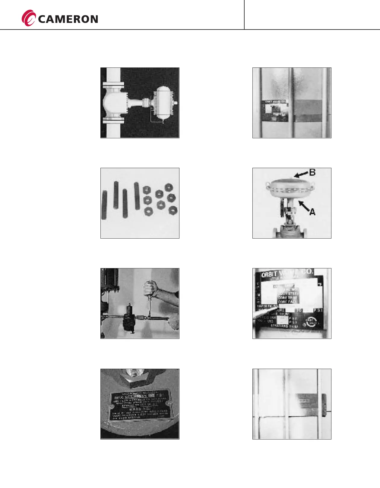
10 ORBIT
actuators can be installed
in the line using standard
studs, nuts and gaskets.
See pages 9 and 10 for
more information.
valves and
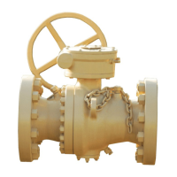
11 After the valve and
actuator unit has been
installed in the line, the
actuator power supply
should be connected.
12 IMPORTANT!
For pneumatic actuators
manufactured by ORBIT,
the supply pressure must be
regulated to the amount
shown on the nameplate.
Failure to comply with this
can damage the unit.
13 Unless otherwise
specified on the nameplate,
the minimum actuator
pressure should always be
within 5 psi, 0.3 bar of
maximum pressure.
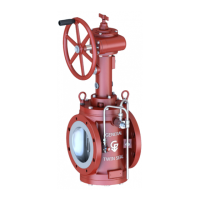
14 Connect the opening
air supply for the
diaphragm actuator to the
bottom point A.
Connect the closing air
supply to the top point B.
15 The first step in
installing an ORBIT Piston
Actuated Valve is to check
the NAMEPLATE to
determine if the actuator is
the LG type or the LS type.
LG or LS will be the first
letters of the actuator
figure number.
For example,
LS-124-D-3-X-S.
16 If the nameplate is
illegible do not attempt to
install without consulting
an ORBIT Representative.
(CONTINUED ON NEXT PAGE)
P R O C E S S V A L V E S
INSTALLATION, OPERATION AND MAINTENANCE
INSTALLATION OF ACTUATED VALVES (CONTINUED FROM PREVIOUS PAGE)
CT-ORB-IOM/6
05/08 ION-3M
®
ORBIT