Instruction manual
Series D multipole size 1
5000026173
Version 00
9
If the device is used to operate an actuator whose accidental movement can generate a hazard,
provide for appropriate locking devices for the moving part of the actuator.
Make sure the connectors are connected and fastened correctly.
Use only power supplies capable of ensuring safe electrical disconnection of the voltage supply
according to IEC 742 / EN 60742 / VDE 0551 with a minimum insulation resistance of 4 kV Protected
Extra Low Voltage (PELV).
It is the user's task to adopt the necessary measures to prevent damage to the system caused by non-
periodic overvoltage peaks on the power lines following power cuts on high energy equipment.
Voltage interruptions are allowed according to the PS2 severity level.
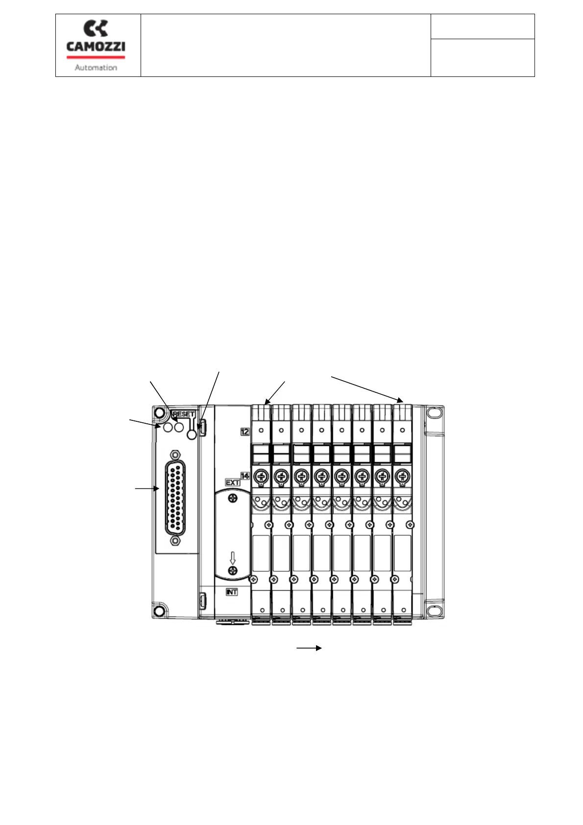
6.1 Connecting and signaling elements
Operating
status LED
Valves Led
Diagnostic
Led
V1
Bobine
V2