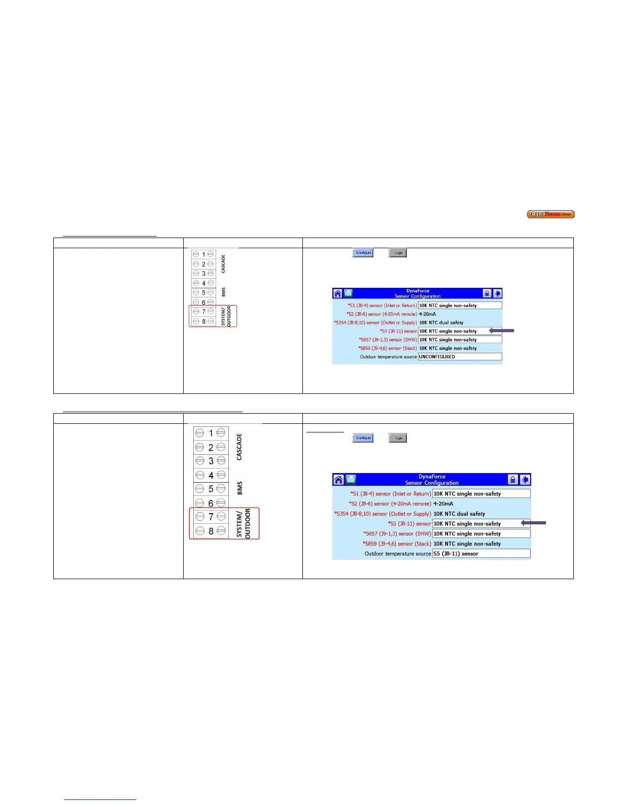
Master Boiler, System Sensor
Master boiler system sensor
configuration
1) Press
and
2) Press [Sensor Configuration]
3) Select S5 (J8-11) Sensor
4) Connector Type: 10K NTC Single Non-Safety
5) The control will proceed into a Lockout 2 condition
6) Press [Verify] > [Begin] > [Yes]
7) Press the reset button on the ignition control within the alotted time
Outdoor Sensor connected to Slave boiler 2 (DRH ONLY)
Slave boiler outdoor sensor
configuration
• When done correctly, the
outdoor temperature will be
shown on the Master boiler
1) Press
and
2) Press [Sensor Configuration]
3) Select S5 (J8-11) Sensor
4) Connector Type: 10K NTC Single Non-Safety
5) The control will proceed into a Lockout 2 condition
6) Press [Verify] > [Begin] > [Yes]



 To Next Page