PART 6 CONTROL PANEL
6.1 APPLIANCE TEMPERATURE CONTROLLER
The appliance is provided with a control panel at the front.
Operating controls are installed inside the control box and are
accessible by undoing the (2) slotted screws and swinging
opening the door. The diagnostic information centre as well as
the on/off switch and the appliance temperature controls reside
on the control box door the ignition control module, VFD,
transformer and relays are mounted on the internal panel.
Figure 24: Touchscreen Display
The SOLA icons will appear in one of four colours indicating
the boiler status:
Colour Description
Blue Normal Operation
Red Lockout Condition
Yellow Holding Mode
Grey Communication Error
The Boiler Temperature Controller for this appliance is the
Honeywell SOLA. It initiates the local call for heat and sets the
target return (appliance inlet) water temperature. This
controller offers a range of operation modes which provides set
point as well as modulating control. It provides the following:
∗ Readings of inlet and outlet water temperatures as well as
flame signal.
∗ Operation as an auto reset limit.
∗ Operation as a control for inlet water temperature, outlet
temperature, system temperature.
∗ 40
o
F T heat exchanger protection algorithm
∗ Available tank mounted sensor used in conjunction with
inlet sensor.
∗ Adjustable; target temp, inter-stage differential, on delay
between stages, minimum on time per stage, minimum off
time per stage.
∗ Display of run hours for maintenance purposes. Counter
wraps around at 10000 hours.
∗ Flame failure signal.
∗ JST and Molex connectors for ease of service.
∗ Error message display in text
∗ Manual override of boiler input rate for combustion
∗ Pump exercising feature runs pump 10 seconds every
three days in the event of no pump operation.
Levels of Access
Two levels of access to simplify the use of the boiler.
User – Access to general boiler and display settings and
adjustments to the central heating, domestic hot water and
lead lag setpoint.
Installer – Access to all user parameters and allows for
changes to additional boiler parameters to allow for ease
of startup and serviceability.
NOTE
Due to the sensitivity of the touchscreen controller, using
the backend of a pen/pencil or stylus is recommended for
accuracy
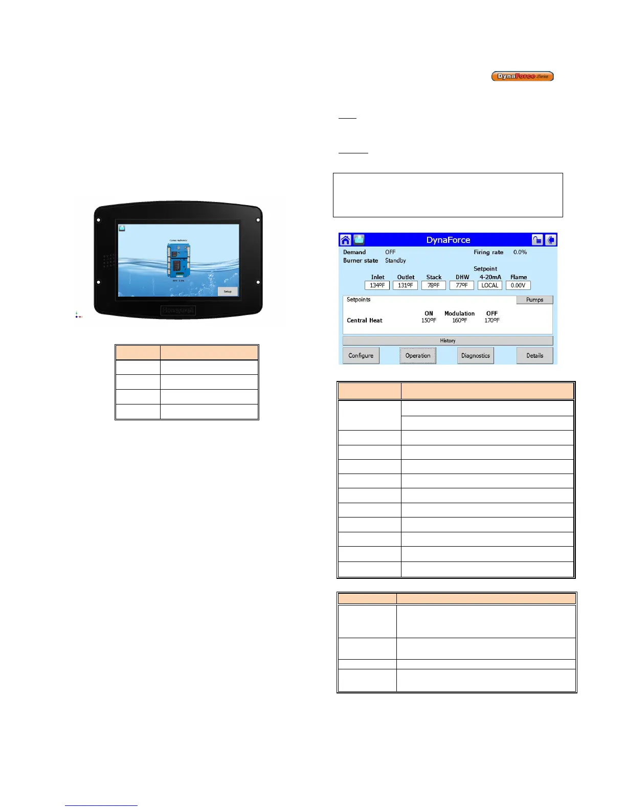
Figure 25: Home Screen
PARAMETER DESCRIPTION
Demand
Central Heating (DRH)
Domestic Hot Water (DRW)
Burner State Current Status of Dynaforce®
Firing Rate Target Firing Rate
Fan Speed Actual Firing Rate (DR300 – 1000)
Inlet Inlet Water Temperature [
o
F]
Outlet Outlet Water Temperature [
o
F]
Stack Stack Temperature [
o
F]
DHW DHW Temperature [
o
F] ], if equipped
Lead Lag/ CH Header Temperature [
o
F], if equipped
Outdoor Outdoor Temperature [
o
F], if equipped
4-20mA 4-20mA input, if equipped
Configure
Access Dynaforce® parameters (CH
Parameters, DHW Parameters, Outdoor
Reset, Pump Configuration etc.)
Operation
Details of boiler operation (Set point, Firing
Rate, Pump Status, Safety circuit)
Diagnostics Manual firing rate, Analog/ Digital Status
Details History, Pump Status, Outlet Temperature