29
Marine Engine Installation Information
Anti-vibration Mount Installation
These mounts are supplied for use where accurate alignment is required, e.g.
between the gearbox output shaft and propeller shaft on marine installations. They
also provide isolation of the power unit, to minimise the transmission of vibration into
the hull.
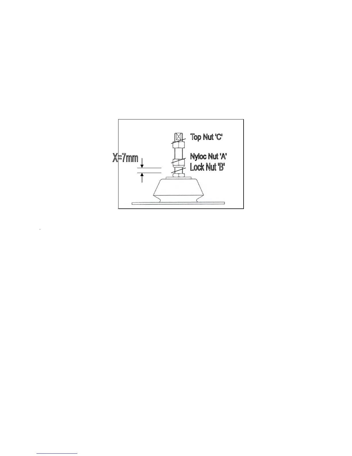
Assembly and adjustment is as below:
X=7mm
Set the gap ‘X’ between the lower face of the Nyloc Nut ‘A’ and the upper face of
Locknut ‘B’ to 7mm.
1. Attach each mount to the engine bearers and secure by tightening Top Nut ‘C’
2. Lower the propulsion unit, complete with mounts onto the beds or support
structure, ensuring that the base of each mounts is fully seated. If any
clearance between the underside of the mounts and beds is found, proceed as
below:
3. (i) If the gap is less than 2mm, re-adjust Nyloc Nut ‘A’, until the base of the
mount contacts the bed face.
(ii) If the gap exceeds 2mm, a separate packing piece / shim should be
fitted.
4. Fit and tighten the bolts fixing the mounts to the bed. Tighten Top Nut ‘C’.
Alignment between the Gearbox and Propeller Shaft Flanges should now be
checked, preferably using a dial indicator for concentricity and feeler gauges for
angular misalignment (see sketch).
Adjust the alignment by raising or lowering the Nyloc Nut ‘A’, to achieve
alignment within the limits of the Gearbox to Propeller Shaft Coupling, as
specified by the manufacturer. If a rigid coupling is used, then it is suggested
that eccentricity should not exceed 0.25mm (0.010”) total indicator reading
and, angular misalignment should be within 0.025mm (0.001”) per 25mm of
flange diameter.