4.9 Remote control 67
In scripted mode, the camera is in the <Alt> state and is running a
script. A signal at the USB port is recorded as a button click under the but-
ton name “remote”, or can be intercepted with a special command. We will
discuss these scripts in section 5.7.5.
4.9.2 Building a simple remote control
In the USB specification, each pin has a special purpose. While electrical
ground is assigned to Pin 4, Pin 1 is used for the supply voltage. The CHDK
interprets the presence or absence of the supply voltage as a signal. You can
test this easily even without a proper remote control. First, enable the
Remote function, then connect a USB cable to the camera and quickly
connect-disconnect-connect the other end to the USB port of a PC. Because
the PC delivers supply voltage at Pin 1, the CHDK will interpret this as a
signal from a remote control and will fire:
USB Pins
Pin Purpose Wire Color
1 VCC (+5V) Red
2 Data – White
3 Data + Green
4 Ground Black
A USB cable release is relatively easy to build. A small battery is needed to
supply a voltage of not more than 5V (Warning: the USB specification al-
lows for a maximum of 5V. Your camera might be damaged if you use a
higher voltage.) The minimum voltage required depends on the camera.
You may find it on the CameraFeatures reference page of the CHDK wiki
(http://chdk.wikia.com/wiki/CameraFeatures). Some cameras are happy
with 3 volts (or even less), but other cameras require up to 4.5 volts.
+
Battery
Switch
1 red
4 black
Type A USB receptable
3 x 1.5 V
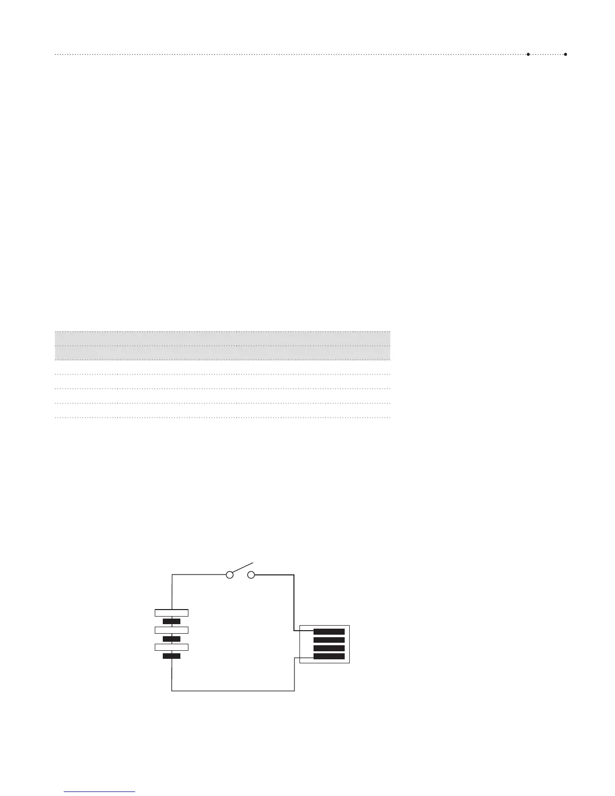
Figure 4-44
Wiring diagram for a USB remote
switch. The battery here delivers 4.5
volts, which should be sufficient for
any camera. This voltage is safe even if
the camera operates at a lower voltage.
The USB specifications require the
camera to tolerate a voltage of 5V or
less at Pin 1. But be sure to get the
polarity of the battery right: wrong
polarity could damage your camera!