COPYRIGHT
©
1999 CANON INC. CANON GP160 REV.0 FEB. 1999 PRINTED IN JAPAN (IMPRIME AU JAPON)
CHAPTER 13 TROUBLESHOOTING
13-3
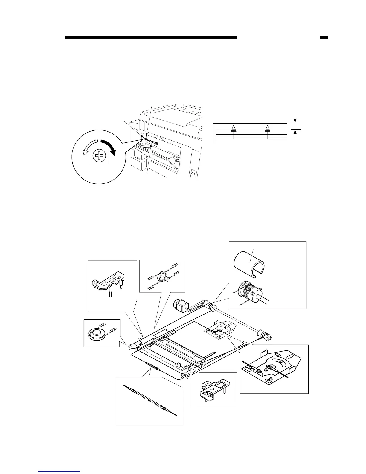
2. Image leading edge margin adjustment
Adjustment when the leading edge of the printed image is out of alignment.
a) Use a precision screwdriver to press down on SW401 and output a test print.
b) Turn VR401 and adjust the leading edge margin of the test print to 4.0 ± 2.0mm.
Figure 13-102
3. Attaching the scanner wire
Attach the wire, following steps 1 to 9. Then perform the mirror positioning adjust-
ment described on the next page.
Figure 13-103
 Loading...