Do you have a question about the Canon GP405 and is the answer not in the manual?
Details copier specifications like speed, resolution, memory, duplexing, and paper sources.
Outlines copier type, board method, resolution, and performance parameters.
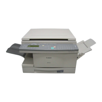
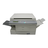
Identifies external components of the copier, including trays and switches.
Explains how to turn on the machine and control its various functions.
Provides instructions for weekly cleaning and basic troubleshooting.
Covers laser light safety, CDRH regulations, handling laser units, and toner safety.
Explains the indirect photostatic reproduction method and its eight steps.
Divides the machine into seven functional blocks: Scanner and Printer Functions.
Explains the functions of CPUs and ICs on the image processor and power supply PCBs.
Outlines direct copying and memory copying sequences, including conditions and operations.
Describes the original exposure system: scanning lamp, mirrors, CCD, and scanner motor.
Explains how the scanner motor drives the mirror mounts and how the home position is detected.
Details the control of the scanning lamp's pre-heating, on/off, and intensity.
Explains size identification using paper sensors and feeder width/length sensors.
Provides general precautions for disassembling and assembling the scanner system.
Describes the image processing system's conversion of optical images to electrical signals.
Details the functions of the CCD PCB, including driving the CCD and A/D conversion.
Explains processing of image signals from analog processing or extension boards.
Describes the laser unit, scanner motor, and BD PCB for laser beam detection.
Explains how the BD signal is used for laser emission start and paper position synchronization.
Details the functions of the laser driver PCB in controlling the laser semiconductor.
Explains the motor's drive signal and speed control mechanisms.
Provides instructions for removing and mounting the laser scanner unit and laser unit.
Shows the construction of the image formation system and its high-voltage controls.
Describes the components of the developing assembly and their rotation.
Explains the drum cleaner's components and waste toner detection.
Provides instructions for disassembling and assembling the drum unit and related parts.
Describes the pick-up/feeding system, sensors, and their functions.
Details the pick-up process from the cassette, including motor and clutch operations.
Explains how the cassette lifter operates to maintain paper stack level.
Describes how the cassette dial and AB/Inch switch identify paper size.
Details the multifeeder mechanism for continuous paper pick-up.
Details inputs/outputs to the deck driver, pick-up operation, and paper detection.
Explains how the paper deck detects jams and indicates them on the control panel.
Provides general precautions for disassembling and assembling the paper deck.
Details major functions of the fixing assembly, including heaters, drive system, and error codes.
Illustrates the drive system of the fixing assembly, showing motor and solenoid connections.
Explains how thermistors and DC-CPU control the main and sub heater drive signals.
Details error detection mechanisms for preventing fixing heater overheating.
Explains the purpose, sequence, bias, and contact of the upper fixing roll.
Describes the control panel's PCBs, LCD, and functions like data communication and LCD contrast.
Lists fan notations, names, functions, and associated error codes.
Explains the 2-speed control of fans based on supply voltage and speed settings.
Details how the machine detects fan errors and indicates them via error codes.
Shows the distribution of power within the machine, including PCBs and voltage outputs.
Details machine counter sensors and their operating conditions, including finisher sensors.
General precautions for disassembling and assembling external covers and panels.
Outlines accessories that can be connected to the machine, like FAX boards and SCSI interfaces.
Provides specifications for the SCSI board, including scan type, memory, and CPU.
General precautions for disassembling and assembling system components.
Details environmental requirements for the machine's location, including temperature and ventilation.
Outlines the steps for unpacking the machine, supplying toner, and setting up components.
Provides instructions for safely moving the machine, including preparing for relocation.
Details the removal and installation of the control panel and associated PCBs.
Instructions for setting DIP switches, connecting boards, and installing the controller.
Provides steps for installing the NE controller, including connecting cables and checking operation.
Lists copier parts that may require periodic replacement due to wear or damage.
Identifies consumables and durable parts for the copier and paper deck.
Outlines scheduled maintenance tasks based on copy count, including cleaning and checks.
Details maintenance actions (clean, replace, lubricate, adjust, inspect) for copier and paper deck units.
Covers image basic adjustment procedures and points of scheduled servicing.
Details adjustments for image quality, exposure, and image formation systems.
Covers initial checks, original issues, parts inspection, and charging assembly checks.
Lists error codes (E000, E001, etc.) and their causes and corrective actions.
Details common feeding issues like paper jams, double feeding, wrinkles, and misfeeds.
Identifies clutches, solenoids, motors, and PCBs, explaining their notation and functions.
Explains methods for upgrading machine components, such as replacing DIMMs or downloading software.
Guides on entering, navigating, and exiting the service mode for diagnostics and adjustments.
Lists self-diagnostic error codes for various machine components and their potential causes.