CHAPTER 6 IMAGE FORMATION SYSTEM
6-8
COPYRIGHT
©
1999 CANON INC. CANON 405/335 REV.0 JAN. 1999 PRINTED IN JAPAN (IMPRIME AU JAPON)
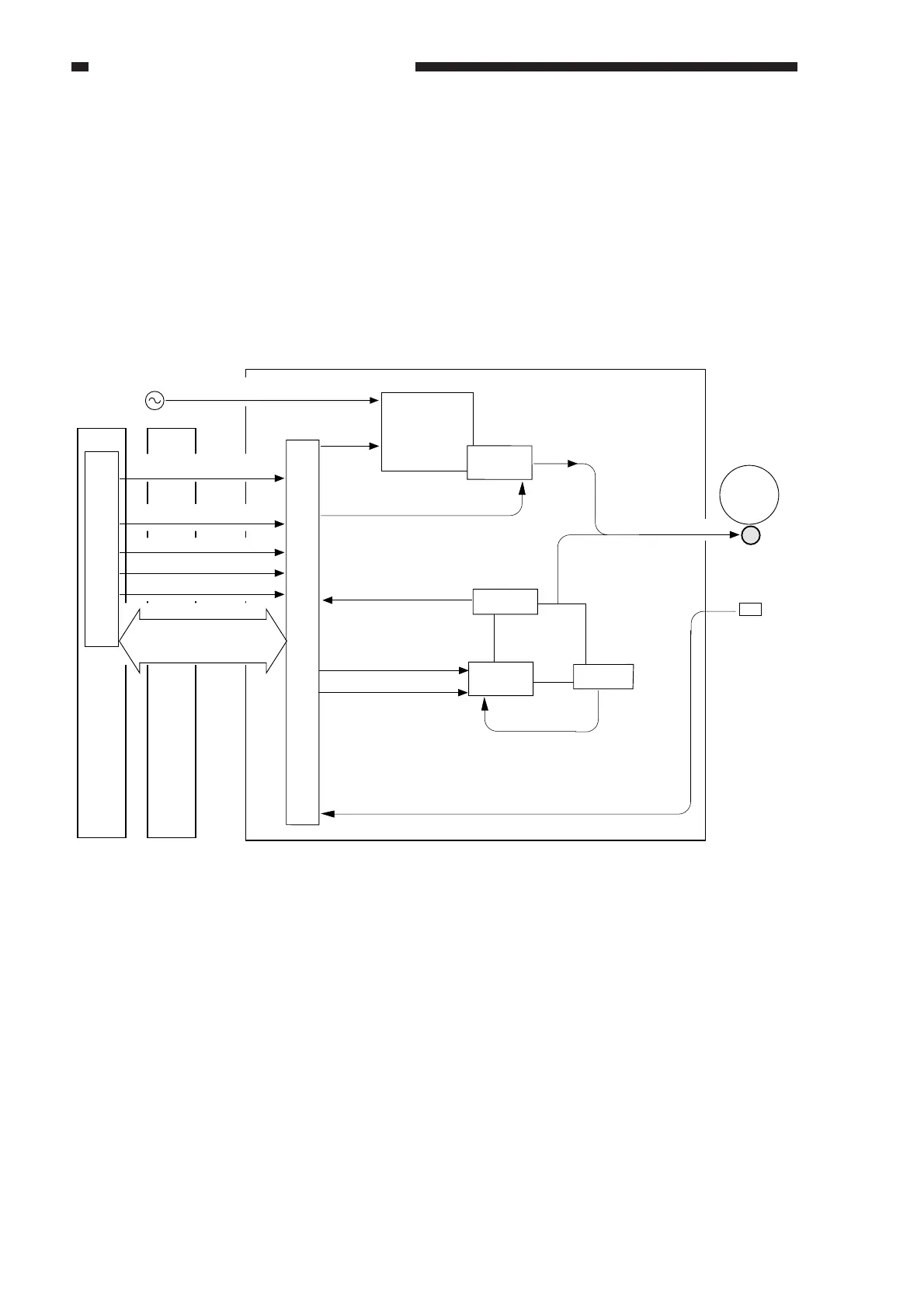
D. Controlling the Transfer Charging Roller Bias
1. Outline
The machine uses a charging roller for direct transfer. A DC bias is applied to the transfer
charging roller, and the mechanism is controlled for the following:
• DC bias constant voltage/constant current
• Application voltage level (correction; ATVC control)
• Output by operation mode
• Output by humidity sensor reading
Figure 6-105
Transfer
charging roller
Photosensitive
DC controller PCB
Image processor PCB
Composite power supply PCB
High-voltage
main transformer
Humidity
detection
AC power supply voltage input
Serial communication
Transfer bias
DC-CPU
CPU
Transfer charging output
enable signal(HVTEN*)
Transformer
drive signal
Constant voltage/constant current
switch signal(HVTSEL*)
Transfer bias ON signal
Transfer bias level signal
Measurement value
Transfer output mode signal 1(HVTM2*)
Transfer output mode signal 2(HVTM1*)
Transfer output mode signal 3(HVTM0*)
Current value
Voltage value
(ATVC measurement value)
Transfer bias control signal
Transfer bias ON signal
Cleaning bias output signal
Cleaning bias
Output
control
High-voltage
transformer for
transfer charging
Drive
control
Current
detection
Voltage
detection
J209BJ103B
J209BJ103B
J209BJ103B
J209BJ103B
J209B
J103B
J209AJ103A
+
drum