CHAPTER 2 BASIC OPERATION PROVIDES
2-8
COPYRIGHT
©
1999 CANON INC. CANON 405/335 REV.0 JAN. 1999 PRINTED IN JAPAN (IMPRIME AU JAPON)
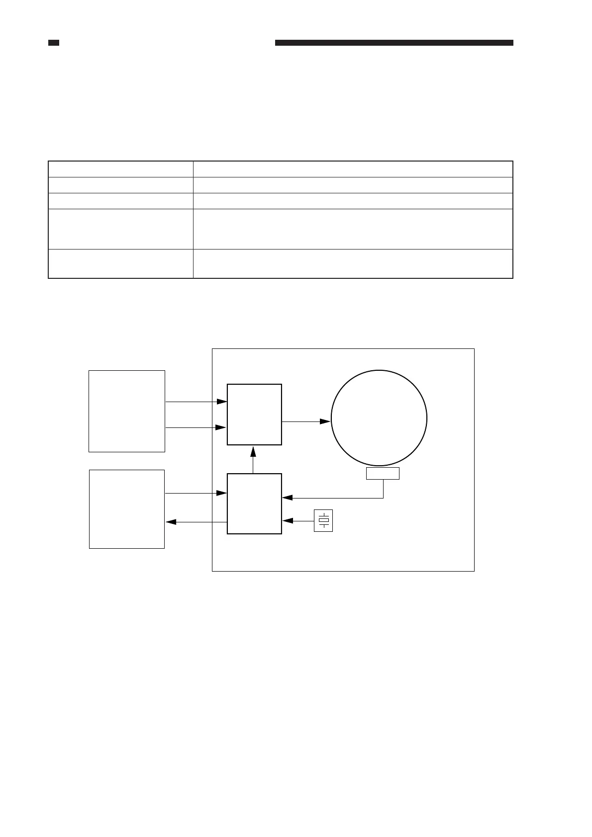
D. Main Motor (M1) Control Circuit
1. Outline
Table 2-104 shows the functions of the main motor control circuit, and Figure 2-105 is a block
diagram of the circuit.
Table 2-104
Item
Power supply
Drive signal
Operating/driving parts
Control
Description
24 VDC from the composite power supply
MMD from the DC controller PCB
Photosensitive drum, registration roller, developing assembly, vertical
path roller, feeding assembly, delivery roller, multifeeder pick-up
roller
• Turns on/off the main motor.
• Controls the main motor to a specific speed.
Clock pulse
generator circuit
Main motor
(M1)
Drive
circuit
Control
circuit
Reference signal
Composite
power
supply PCB
+24V
0V
DC controller
PCB
MMD
M1LCK
Motor driver PCB
Figure 2-105