CHAPTER 9 FIXING SYSTEM
9-6
COPYRIGHT
©
1999 CANON INC. CANON 405/335 REV.0 JAN. 1999 PRINTED IN JAPAN (IMPRIME AU JAPON)
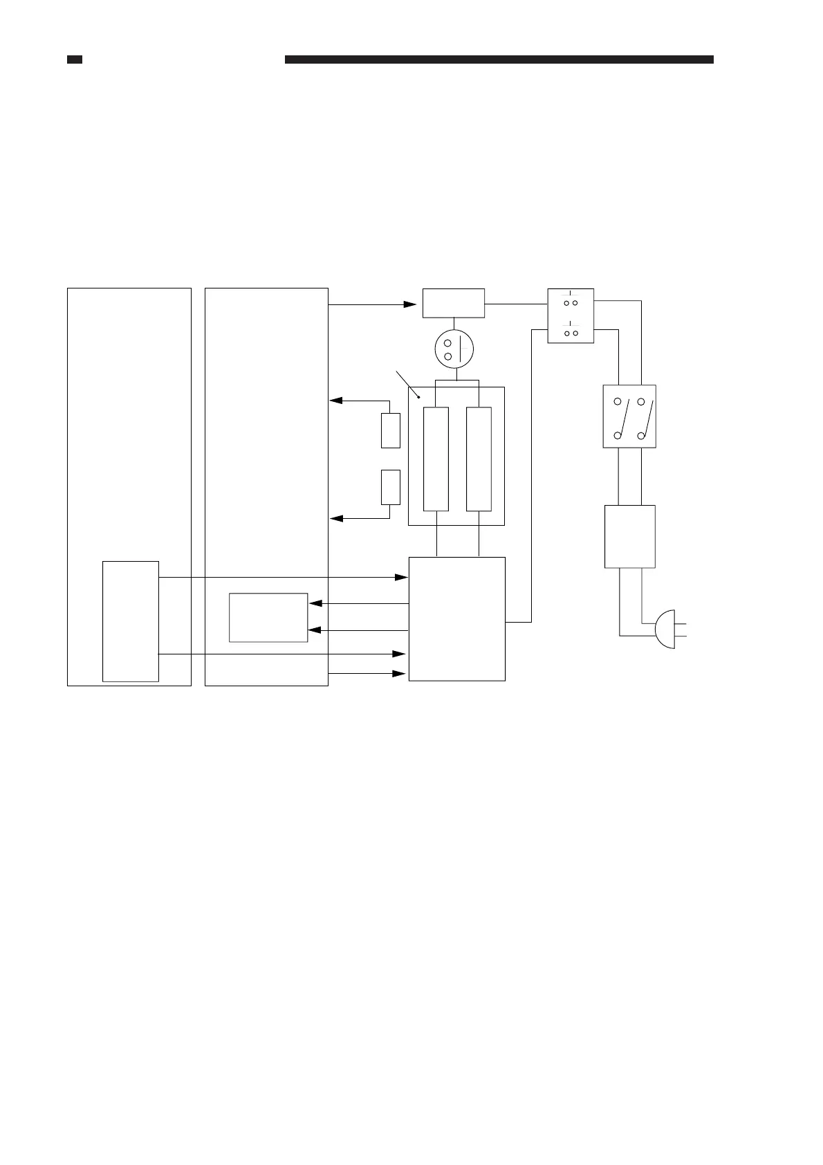
C. Controlling the Fixing Temperature
1. Outline
The temperature of the copier's upper fixing roller is monitored by the main thermistor (TH1)
and the sub thermistor (TH2), and is controlled by the DC-CPU*, which varies the main heater
drive signal (H1-D) and the sub heater drive signal (H2-D) according to the levels of TH1 and TH2.
DC
-CPU
Image processor PCB
DC controller PCB
RL1
THSW1
Leakage
power
breaker
Error
detection
circuit
SSR
TH2
TH1
H1 H2
Upper fixing roller
Main power
switch
Door switch
SW2
SW1
H1-D
H2-D
H1-ERR
H2-ERR
0V
TH1-S
RL-D
TH2-S
Figure 9-103 Major Parts Used for Fixing Temperature Control