EasyManua.ls Logo

Canon GP405 - Inputs to and Outputs from the Major Pcbs

Canon GP405
682 pages
Print Icon
To Next Page IconTo Next Page
To Previous Page IconTo Previous Page
Loading...
CHAPTER 2 BASIC OPERATION PROVIDES
2-10
COPYRIGHT
©
1999 CANON INC. CANON 405/335 REV.0 JAN. 1999 PRINTED IN JAPAN (IMPRIME AU JAPON)
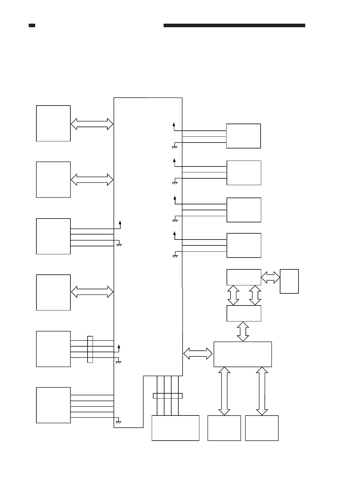
E. Inputs to and Outputs from the Major PCBs
1. Image Processor Circuit
• Inputs to and Outputs from the Image Processor Circuit
Figure 2-106
Image processor PCB
Control Card
V (accessory)
5V
J709
-2
-3
-4
-5
5V
J708
-1
-2
-3
-4
J510
-4
-3
-2
-1
See Figure 5-201.
BD (input)
J461
J500 J717
Laser driver
PCB
J113 J714
DC controller
PCB
Checks are not
possible in the field,
and explanations
are omitted.
J301 J706
J712
J711
J703
J704
Analog
processor
PCB
Beam
detection (BD)
PCB
Fax battery
board
J718
-1
-2
-3
-4
-5
Original size
sensor 0
5V
5V
5V
5V
DSZ0
DSZ1
DSZ2
DSZ3
Checks are not
possible in the field,
and explanations
are omitted.
Low-voltage power
supply PCB
Original size
sensor 2
Original size
sensor 1
Original size
sensor 3
Fax board
System mother board
J8002
J8005
J715
J716
J8004
J8301
J8101
J8003
J8202
J8102
J8203
J8204 J8
J8103
SCSI
Interface
board
J8006
J8501
PDL
I/F board
Printer mother
board
Printer
board
J603
J701
1234
1234
J440
5.1V
3.4V

Table of Contents