COPYRIGHT
©
1999 CANON INC. CANON 405/335 REV.0 JAN. 1999 PRINTED IN JAPAN (IMPRIME AU JAPON)
6-1
CHAPTER 6 IMAGE FORMATION SYSTEM
I. OUTLINE OF IMAGE FORMATION PROCESS
A. Outline
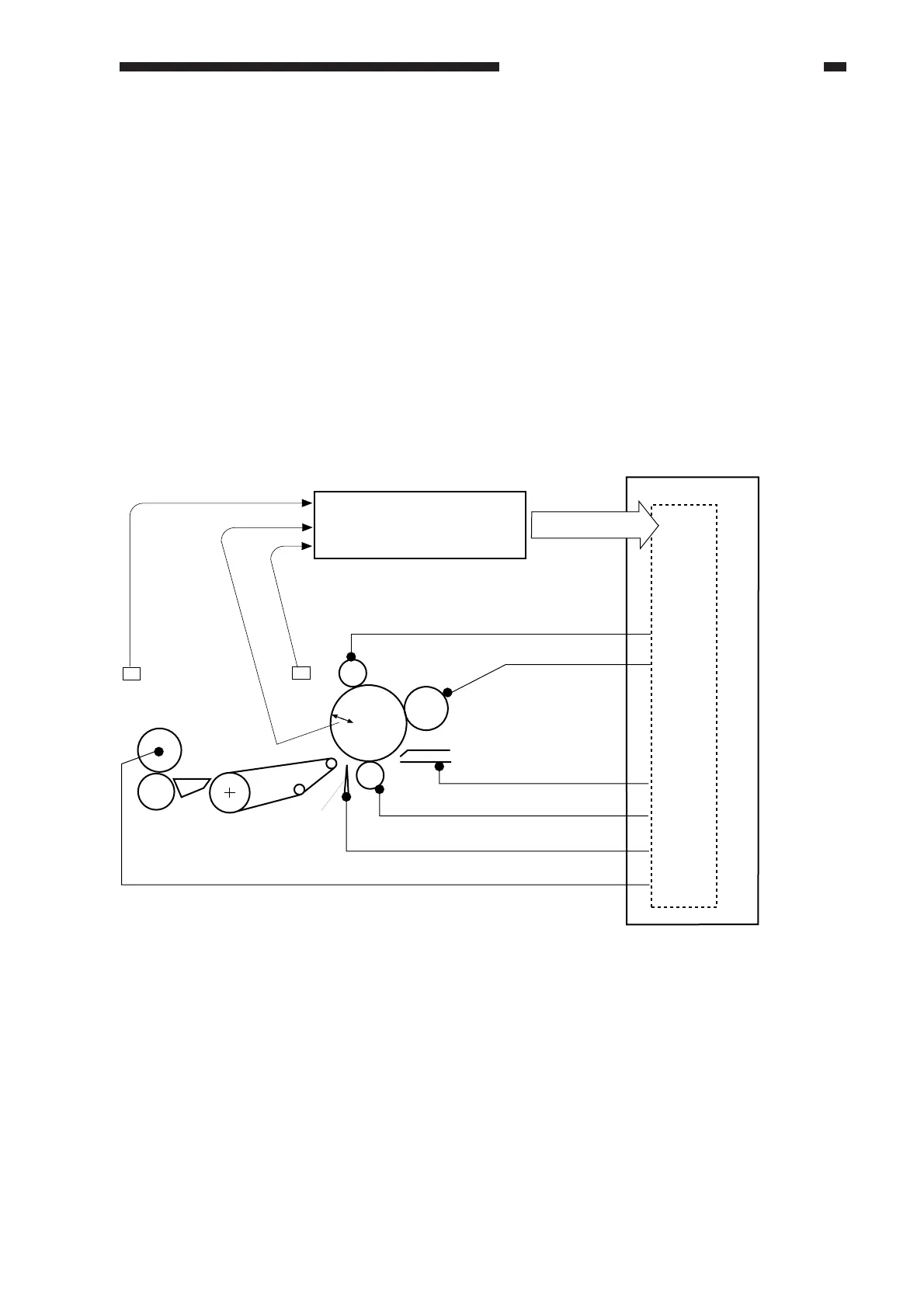
Figure 6-100 shows the construction of the image formation system. Each high-voltage
mechanism is controlled by the high-voltage transformer circuit on the composite power supply
PCB based on the control signals from the image processor PCB for the following items:
• Primary charging roller bias
• Transfer charging roller bias
• Separation static eliminator constant current
• Developing bias
• Transfer guide bias
• Upper fixing roller bias (See Chapter 9 "Fixing System.")
Figure 6-100
Composite power supply PCB
Image processor PCB
Photosensitive
drum
Primary charging roller
Developing assembly
Transfer guide
Transfer charging roller
Separation
static
eliminator
Upper
fixing roller
High-voltage transformer circuit
Control signal
Humidity
sensor
Temperature
sensor
Resistance