COPYRIGHT
©
1999 CANON INC. CANON 405/335 REV.0 JAN. 1999 PRINTED IN JAPAN (IMPRIME AU JAPON)
14-29
CHAPTER 14 TROUBLESHOOTING
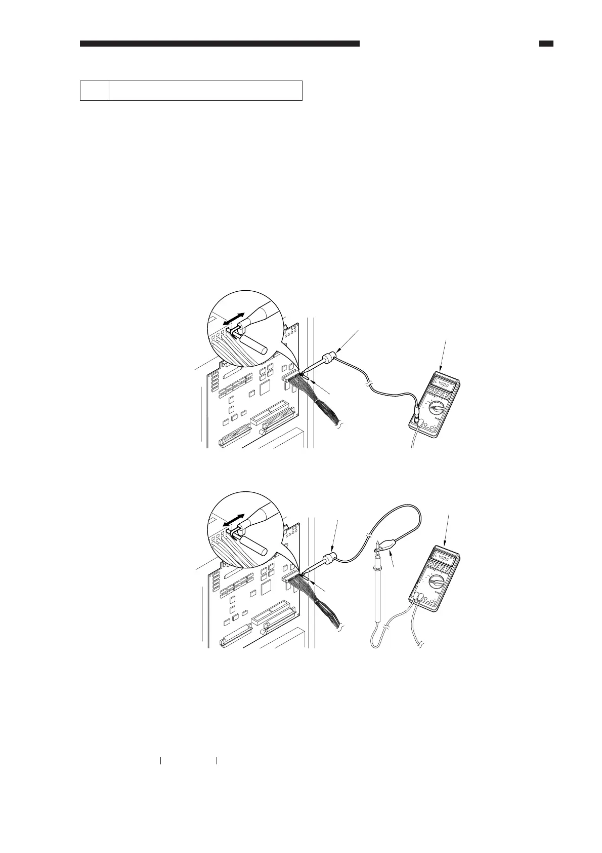
5 Checking the Photointerrupters
The photointerrupters may be checked in either of the following two methods:
a. Using a meter.
b. Using service mode (I/O mode).
a. Using a Meter
You cannot insert the meter probe directly into the connectors of the machine's PCBs, as they
are designed specially to enable smooth connection. Obtain a probe extension tool (FY9-3038-000/
FY9-3039-000).
1) Set the digital multimeter range to 12 VDC.
2) Connect the meter probe to GND (0 VDC) of the DC controller PCB.
3) Make a check as indicated. (Use the probe extension and the clip as necessary.)
Figure 14-235
b. Using Service Mode
1) Start service mode.
2) Press COPIER>I/O, and select DC-CON.
The bit number notations in the tables that follow represent the following:
Pinch the pin
7537
04
DIGITAL
MULTIMETER
YOKOGAWA
POWER
OPEN
TERMINAL
SHUTTER
20
kHz
10
A
COM
V•
É
•
mA•É A
10A
mA
0
2
4
2
REL/%
AVG
SELECT
RANGE
MIN/MAX
DATA-H
4
D•H
Å|
Å{
mV
mV
Å}
+
Å`
/
LoHz/rpm
/Å`/ADP/KÅé
V
Å`V
Hz
/
Åé
É
É A
FUSED
FUSED
1000V
MAX
!
TRUE RMS
0.1% V
/Å`/Hz
Probe extension
Probe extension
Meter
Meter
Pinch the pin.
7537
04
DIGITAL
MULTIMETER
YOKOGAWA
POWER
OPEN
TERMINAL
SHUTTER
20
kHz
10
A
COM
V•
É
•
mA•É A
10A
mA
0
2
4
2
REL/%
AVG
SELECT
RANGE
MIN/MAX
DATA-H
4
D•H
Å|
Å{
mV
mV
Å}
+
Å`
/
LoHz/rpm
/Å`/ADP/KÅé
V
Å`V
Hz
/
Åé
É
É A
FUSED
FUSED
1000V
MAX
!
TRUE RMS
0.1% V
/Å`/Hz
Clip
FY9-2004-000
(FY9-3038)
FY9-2003-000
[ Connection 1 ]
[ Connection 2 ]
ex.P001 00000000
bit7 bit0
 Loading...