(17/23)
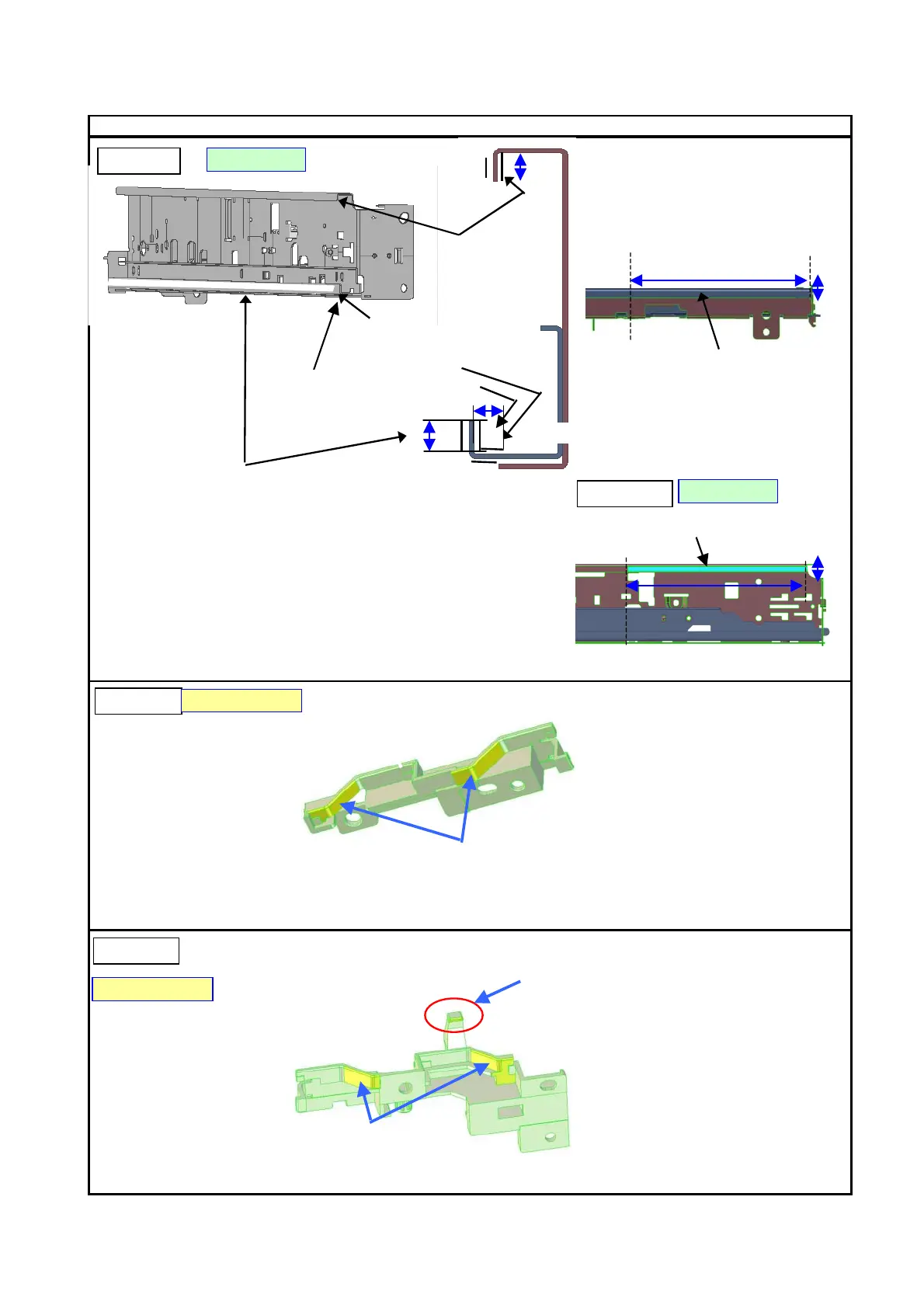
2-4. Grease Application
Location & Grease Amount
5
4
②
②
Printer Unit
FLO IL K G -107A
Main Chassis
FLO IL K G -107A
100
100
Grease to be applied to the area 1.2 mm
from the bottom to 4.2 mm.
Grease can extend to the area 0.7 mm
from the bottom to 1.2 mm, and from 4.2
mm to 4.7 mm.
Entire surface
Bottom surface of the rail (Z):
9 to 18 mg x 1 location
Back surface of the chassis (Y):
155 +/- 20 mg
25 mm from the both ends (X)
can be left without grease.
Inner bottom surface of the rail (Z):
450 +/- 45 mg
10 mm from the both ends (X) can
be left without grease.
Back surface of the rail (Y):
150 +/- 15 mg
10 mm from the both ends (X)
can be left without grease.
Front surface of the rail (Y):
220 +/- 20 mg (200 to 240 mg)
10 mm from the both ends can
be left without grease.
Front surface of the chassis (Y):
9 to 18 mg x 1 location
Entire surface
2.35 mm from the top edge to 3.85 mm
PG cover B cam surface (yellow area in the diagram):
4.5 to 9 mg x 2 locations
PG Cover B
M O LY K O T E P G -641
PG Cover F
M O LY K O T E P G -641
PG cover B cam surface (yellow area in the diagram):
4.5 to 9 mg x 2 locations
Cam surface contacting the Cap Holder Col:
1 to 3 mg film x 1 location