Chapter 4
4-2
4.2 Disassembly/Reassembly
4.2.1 Disassembly/Reassembly
0014-8946
See Parts Catalog for the process of disassembly and reassembly except for the following main units.
Main units are the following four units.
1.Carriage unit
2.Ink tube unit
3.Purge unit
4.Ink tank unit
The parts layout illustrations in parts catalog have figure numbers according to the disassembly procedure of the product.
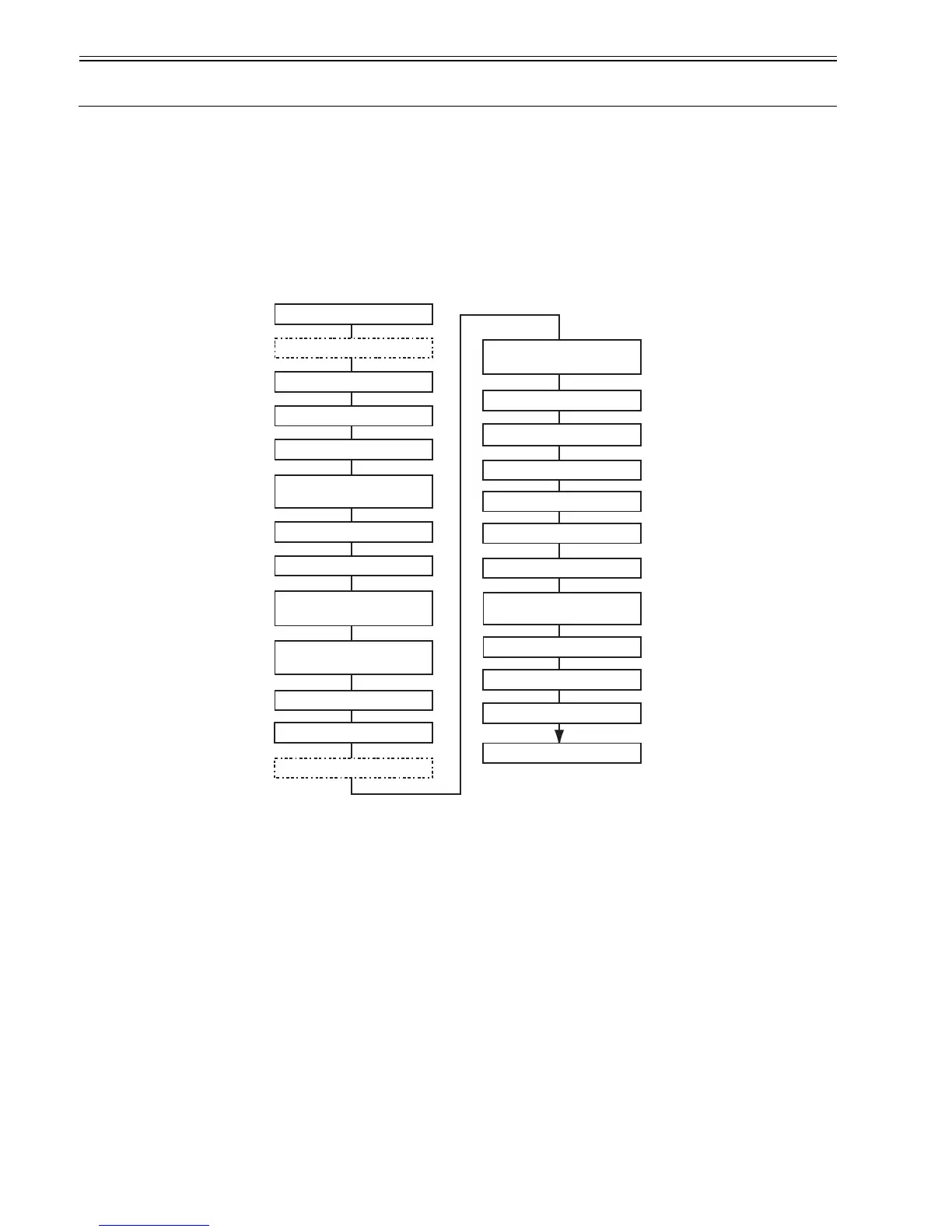
Main unit disassembly and assembly flows
* Ink drainage in a dotted line performs manual or automatic either.
F-4-2
<Legend > c: Connector h: Hook s: Screw
Printer
Automatic ink drain
Manual ink drain
Left/right circle cover (L) (h1)
Left/right circle cover (S) (h1)
Left/right side covers (s3, h2)
Left/right tank cover units
(s3)
Upper rear cover (s5)
Upper cover
Open left/right ink tank units
(s4)
Upper left/upper right covers
(h1)
Rear cover right (s4)
Rear cover left (s2)
Left/right printheads
Left/right joint bases
Ink tube joint
Ink tube cover (s2)
Flexible cable (c3)
Carriage PCB cover (s4)
Carriage unit
Move the carriage to
above the platen
Head management sensor
(s1)
Lift unit (s5)
Cutter unit
Pulley base (s3)
1. Carriage Unit Disassembly Flow
 Loading...