Chapter 7
7-2
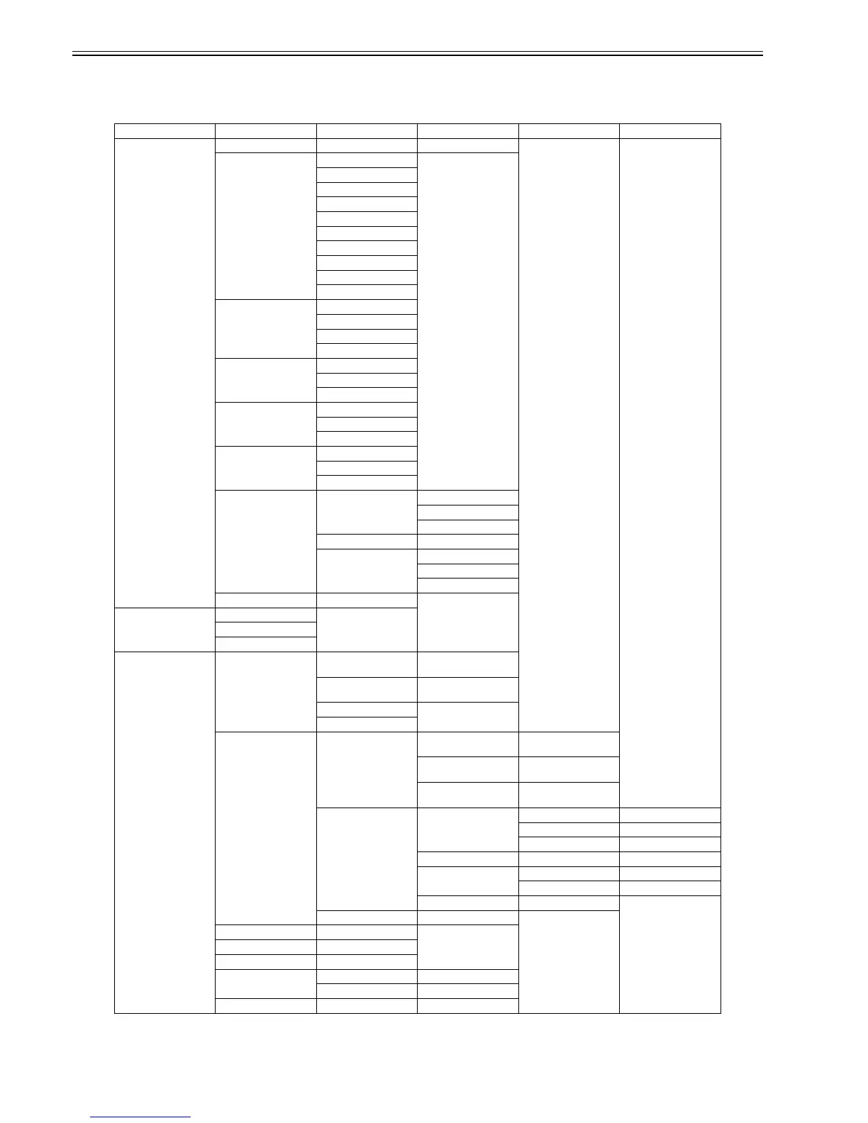
7.1.2 Map of the Service Mode
0025-0482
The hierarchy of menus and parameters in the Service Mode is as shown below.
T-7-1
First Level Second Level Third Level Fourth Level Fifth Level Sixth Level
DISPLAY PRINTINF YES/NO : Select YES to print
SYSTEM S/N
TYPE
LF TYPE
TMP
RH
SIZE LF
SIZE LF
SIZE CR
SIZE CR
AFTER INST
HEAD S/N L
S/N R
LOT L
LOT R
INK PC
---
BK
WARNING 01
---
20
ERROR 01
---
20
JAM 01 1:
---
4:
---
05 1:
---
4:
INK CHECK 0 0 0 0 0 0 0 0 0 0 0 0
I/O DISPLAY I/O DISPLAY 1
I/O DISPLAY 2
I/O DISPLAY 3
ADJUST PRINT PATTERN NOZZLE 1 : Press the [OK] button to
execute
OPTICAL AXIS : Press the [OK] button to
execute
LF TUNING
LF TUNIG 2
HEAD ADJ. MANUAL HEAD ADJ EXTENSION : Press the [OK] button to
execute
DETAIL : Press the [OK] button to
execute
BASIC : Press the [OK] button to
execute
ADJ. SETTING A A-1 : Adjustment value entry
---
A-48 : Adjustment value entry
---
F F-1 : Adjustment value entry
F-2 : Adjustment value entry
SAVE SETTINGS YES/NO
RESET SETTINGS YES/NO
NOZZLE CHECK POS. YES/NO
GAP CALIB. YES/NO
CHANGE LF TYPE 0/1
CR REG EXECUTE YES/NO
RESET YES/NO
CR MOTOR COG YES/NO
 Loading...