Do you have a question about the Canon iR3570 and is the answer not in the manual?
| Print Technology | Laser |
|---|---|
| Type | Multifunction |
| Functions | Print, Copy, Scan, Fax |
| Max Paper Size | A3 |
| Duplex Printing | Yes |
| Copy Resolution | 600 x 600 dpi |
| Scanner Type | Flatbed, ADF |
| Scan Resolution | 600 x 600 dpi |
| Fax Speed | 33.6 Kbps |
| Network Connectivity | Ethernet 10/100Base-TX |
| Interface | USB 2.0, Ethernet |
| Dimensions | 565 x 700 x 761 mm |
| Print Speed | 35 ppm |
| Print Resolution | 2400 x 600 dpi |
| Paper Capacity | 550 sheets |
| Supported Paper Sizes | A3, A4, A5 |
| Copy Speed | 35 cpm |
| Zoom Range | 25% - 400% |
| Memory | 256 MB |
| Connectivity | USB, Ethernet |
| Hard Drive | 20 GB |
| Operating System Compatibility | Windows, Mac, Linux |
| Monthly Duty Cycle | Up to 150, 000 pages |
Explains the meaning of various symbols used in the documentation to indicate special information.
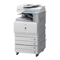
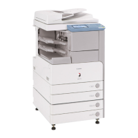
Details the various system configurations, including delivery, output, pickup, and printing accessories.
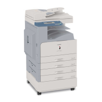
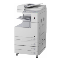
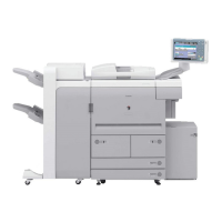
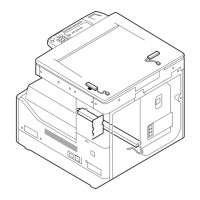
Outlines the machine's specifications, external views, cross-sections, and usage instructions.
Explains basic maintenance tasks for users, including cleaning and inspection procedures.
Covers crucial safety information related to laser light, CDRH regulations, and toner handling.
Outlines essential pre-installation checks for site environment, power, and room conditions.
Provides step-by-step instructions for unpacking machine components and installing them.
Details procedures for verifying network connectivity using PING and remote host addresses.
Offers solutions for common network issues, including suspected causes like faulty connections or settings.
Guides on checking image quality and machine operation after installation.
Provides installation procedures for the card reader, including checking contents and points to note.
Outlines the procedure for installing the NE Controller-A1, emphasizing compliance and pre-installation checks.
Details the installation procedure for the reader heater, including parts check and host machine preparation.
Explains the installation process for the cassette heater and its related components.
Provides instructions for installing the cassette heater onto the cassette pedestal.
Details the installation procedure for the deck heater, including parts check and host machine preparation.
Guides through the installation of the voice guidance kit, covering package contents and precautions.
Outlines the installation procedure for the voice operation kit, including prerequisites and checks.
Describes the functional construction and major PCB wiring diagrams of the machine.
Explains the basic sequence of operation, particularly during power-on.
Details the construction and functions of the main controller, including components and electrical circuitry.
Explains the electrical circuitry and PCB layouts, focusing on the main controller PCB.
Describes the step-by-step process of the machine's startup sequence, including software loading.
Outlines the procedure for safely shutting down the machine, especially regarding HDD access.
Explains the overview of the image flow and the construction of the image processing module.
Details the flow of image data for various functions like copy, box, SEND, and fax transmission/reception.
Provides detailed instructions for replacing key components such as the main controller PCB, SDRAM, boot ROM, and HDD.
Details specifications, control mechanisms, functions, major components, and control system construction.
Explains the basic sequences of operation, including power-on and response to start key presses.
Covers controls related to the scanner drive system, contact image sensor, enlargement/reduction, size identification, and dirt sensor.
Provides instructions for replacing components like copyboard glass, reader controller PCB, scanner motor, and contact sensor.
Details specifications, control mechanisms, functions, major components, and control system construction.
Explains the basic sequence of operation for the laser exposure system.
Covers controls related to laser activation timing, intensity, scanner motor, and shutter.
Provides instructions for replacing parts of the laser scanner unit, including covers and the laser unit.
Details specifications, major components, and control system construction for the image formation system.
Explains the image formation process, including outline and detailed steps.
Describes the basic sequences of operation for initial rotation, copying, and last rotation.
Covers control mechanisms for image stabilization, including APVC and ATVC control.
Details the charging mechanism of the drum unit and the primary charging roller cleaning.
Explains the photosensitive drum cleaning process.
Covers control mechanisms for the developing bias.
Provides an overview, route of toner supply, and control mechanisms for the toner cartridge.
Details the outline, control mechanisms, and cleaning procedures for the transfer unit.
Covers transfer guide bias control.
Explains the process of photosensitive drum cleaning, including waste toner collection and checking.
Provides detailed steps for replacing various parts related to image formation, such as lamps, units, and sensors.
Details specifications, controls, functions, blocks, roller arrangements, paper paths, sensors, and drive routes.
Explains basic sequences, speed increases, acceleration intervals, and detecting jams.
Covers detection of delay jams, stationary jams, and other jam types.
Provides an overview, basic sequence, paper size identification, universal cassette setup, and paper level sensor information.
Details overview, basic sequence, paper size identification, and paper retaining mechanism.
Covers overview and checking horizontal registration.
Explains overview, sequence of image formation, and paper flow for duplex feeding.
Provides detailed instructions for replacing various parts within the pickup/feeding system, such as pickup units, rollers, sensors, and motors.
Details specifications, control mechanisms, functions, major components, and control system construction.
Explains the power-on and down sequences for the fixing system.
Covers controls for fixing film speed, temperature, cleaning, and paper passage detection.
Details protective mechanisms and error detection for the fixing system.
Provides instructions for replacing components of the fixing unit, including the fixing film, pressure roller, and cleaning roller.
Covers overview, LCD indication processing, adjustment, and functions of the control panel and its CPU.
Explains the overview and timing of counter increments for various printer units.
Details the overview, 2-speed control, and sequence of operation for the machine's fans.
Covers power supply routes, rated outputs, protection functions, backup battery, and energy-saving functions.
Provides detailed instructions for replacing various parts of the machine, including main drive assembly, power supply units, control panel components, DC controller PCB, and inverter PCBs.
Covers standards for image position and procedures for adjusting image position for various paper sources.
Addresses adjustments required after CIS or reader controller PCB replacement or RAM initialization.
Details adjustments after replacing the laser scanner unit.
Covers adjustments after replacing the developing unit or drum unit.
Lists electrical components that may require adjustment or replacement, such as HDD, DC controller PCB, main controller PCB, and reader controller PCB.
Explains adjustments for horizontal registration when replacing cassettes or duplex units, and manual feed pickup horizontal registration.
Guides through initial checks related to site environment, paper, durable parts, and functional systems.
Provides comprehensive troubleshooting for image faults, malfunctions, printing/scanning issues, network problems, and transmission/fax issues.
Presents a comprehensive table of error codes, their names, causes, and remedies.
Provides detailed explanations for specific error codes, including their causes and remedies.
Lists error codes related to the SEND function and provides results of self-diagnosis.
Categorizes jam codes by unit (printer, finisher, ADF) and provides details on their causes and remedies.
Lists alarm codes and their corresponding descriptions and remedies.
Details specific error codes for finisher and saddle finisher units, including causes and remedies.
Lists error codes specific to the DADF unit and provides detailed causes and remedies.
Explains the construction of service mode, including starting, ending, backup, and initial screens.
Details how to navigate and interpret information displayed in the status display mode for copier, feeder, and sorter.
Explains the I/O display mode, including outline and specific I/O types like DC-CON, R-CON, FEEDER, and SORTER.
Covers adjustment modes for copier, feeder, and sorter, including specific adjustment items and their descriptions.
Details operation and inspection modes for copier and feeder, listing various functions and their parameters.
Explains machine settings modes for copier, feeder, sorter, and board, detailing various configuration options.
Covers test print modes for copier, providing lists of available test prints.
Explains counter modes and lists available copier counters.
Provides an outline of machine upgrading and the service support tool.
Covers steps for preparing to upgrade, including registering system software and making connections.
Details procedures for formatting all or selected partitions of the HDD.
Explains how to download system software, including outlines and procedures for various components like System, RUI, SDICT, MEAPCONT, KEY, BOOT, Dcon/Rcon, G3 FAX, and Backup Data.
Lists necessary special tools, oils, and solvents required for servicing the machine.