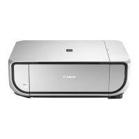
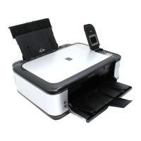
Do you have a question about the Canon MP540 and is the answer not in the manual?
Details errors indicated by Alarm LED and LCD messages.
Explains errors indicated by blinking LEDs and error codes.
Lists warnings displayed on the LCD during operation.
Procedures to enter and operate the service mode using the Service Tool.
Describes user-accessible functions for maintenance and checks.
Guides for disassembling external housing, scanner unit, and covers.
Illustrates and lists items included in the packaging.
Shows the AC adapter used with the unit.
Details the external covers and the scanner assembly.
Shows the components of the document pressure plate.
Explains the parts of the operation panel and its components.
Illustrates the main chassis and front door assembly.
Details the bottom case and ink absorber assembly.
Shows the main logic and sensor board assemblies.
Illustrates the components of the sheet feed mechanism.
Details the carriage and pressure roller assemblies.
Shows the platen and spur unit components.
Details the purge and switch system units.
Lists optional items and consumables, specifically ink tanks.
Identifies the lubrication tool used for maintenance.
| Print Technology | Inkjet |
|---|---|
| Print Resolution | 9600 x 2400 dpi |
| Scanner Type | Flatbed |
| Scanner Resolution | 2400 x 4800 dpi |
| Copy Resolution | 600 x 600 dpi |
| Paper Capacity | 150 sheets |
| Connectivity | USB 2.0 |
| Paper Sizes | A4, A5, B5, Letter, Legal, Envelopes |
| Ink Cartridges | 5 individual ink tanks |
| Media Card Support | CompactFlash, Memory Stick, Memory Stick PRO, SD, SDHC, MMC |
| Display | 2.0-inch LCD |
| Operating Systems | Windows, macOS |


