8
Installing the extractor
1.
Before carrying out the appliance
installation, please check that all
components are not damaged, in such a
case contact your retailer and do not
continue with the installation operation.
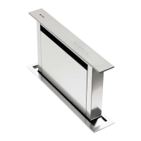
Before the installation of the
Downdraft, please remove the safety piece
you can see in the picture (Fig. 1).
Furthermore, please read carefully all of the
following installation instructions.
The manufacturer shall not be deemed
responsible for air capacity or noise problems
caused by failure to comply with the above
instructions and no warranty on the product
shall be provided.
2.
Before making the hole, check that there are
no structural or other parts inside the
cabinet where the appliance is to be
placed, which could hinder the correct
installation. Check that the dimensions of
the Downdraft and the ones of the hob are
compatible with the cabinet so that the
installation can be carried out properly.
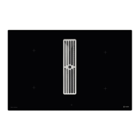
3.
Make a rectangular opening in the back part
of the cook top (842x100mm for the 90 cm
model and 542x100mm for the 60 cm
model). If the DDMEXT10 is already installed,
remove the screws and the motort in order
to insert the downdraft in the hole made.
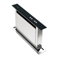
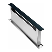
4.
Put the Downdraft in the opening, inserting
it from above as shown in (Fig. 2).
5.
Fix the downdraft inside the cabinet, using
the special fixing brackets supplied with the
product (Fig. 3).
Insert the brackets in the lower side of the
downdraft (Fig. 3), in such a way that there
is a 2 mm distance between the lower side
of bracket and the bottom of the cabinet
(Fig. 3).
This distance will allow the traction to be
positioned downwards of the product, at
the moment of fixing, in order to have the
stainless steel trim perfectly adhering with
the work surface. Before inserting the
screws, please make sure that the appliance
is perfectly perpendicular with the work
surface.
6.
Once the installation is complete and after
connecting the appliance to the mains
power, lift up the downdraft and remove the
door block (Fig. 4); then open the door
(Fig. 5) and fit the filters in place (Fig. 6). In
the version of the Downdraft using the the
DDMEXT10, install the power unit orienting
the air outlet to the desired position, either
downwards or upwards (Fig. 7).
The motor can be installed either on the front
or rear side of the downdraft. After having
installed the motor, then connect the air
ducts.
7.
For versions using an external motor, place
the external motor in a suitable area and fit
the exhaust air flue as illustrated. Then fit
the air outlet ducts between the external
motor and the downdraft. Select an air
outlet from the five possibilities (Fig. 8) and
fit the union supplied with the appliance.
8.
Place the metal box containing the wiring in
an easily accessible area to allow main-
tenance interventions where necessary
(Fig.9). Connect the connectors (9-pole
connector) to control the actuator and
safety control and button pad connector)
(Fig. 10).
- Use an air exhausting pipe/ducting not
exceeding a maximum lenght of 5 meters
- Do not use flexible ducting
- Limit the number of elbows in the piping, as
each elbow reduces the air capacity of 1 linear
meter. (for example, if you use 2 90 degree
elbows, the length of the piping should not
exceed 3 metres.
- Avoid abrupt direction changes
- Use a 150mm constant diameter ducting pipe
for the whole length (or equal surface area.
- Only use ducting approved by the standards
in force.