support@carbide3d.com docs.carbide3d.com 10/02/2020 Version 1.0
c. Connectors are polarized. Be sure to align them properly.
3. Re-install the enclosure cover.
Shapeoko 3 Instructions
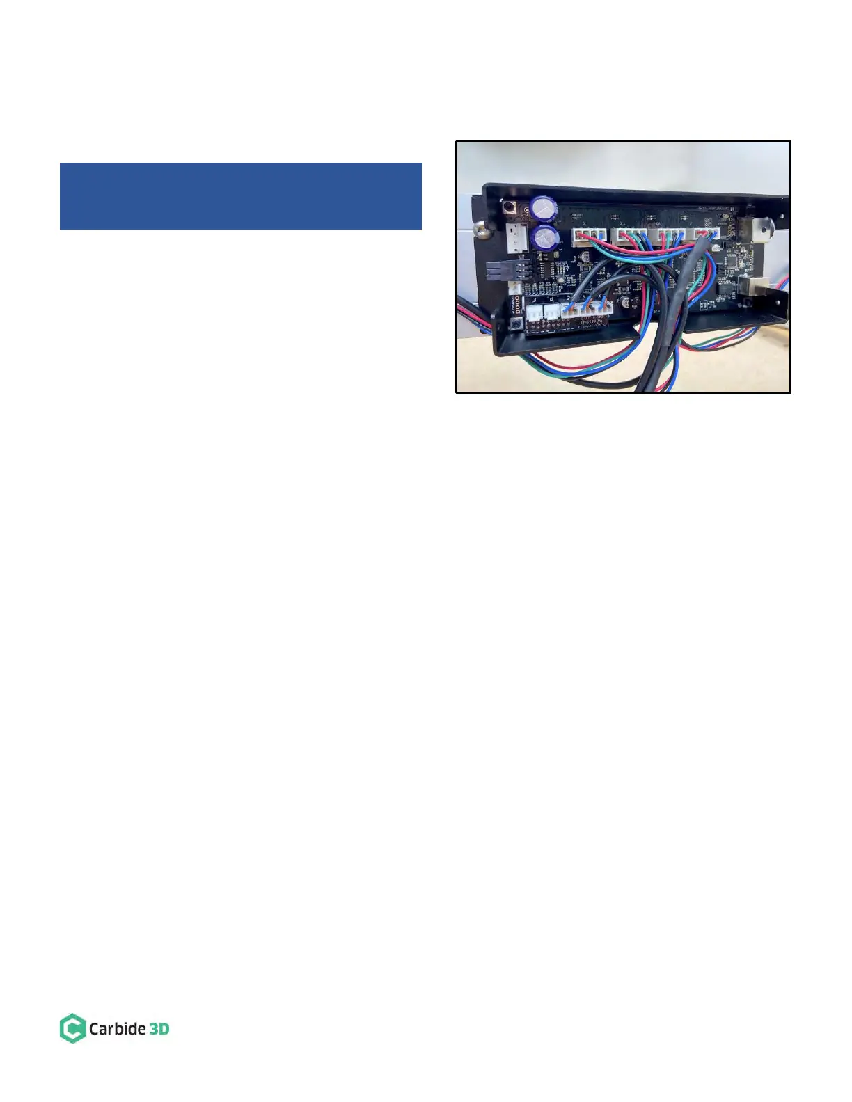
1. Plug the PCB riser board into the Carbide Motion
board. See Fig. 20.
a. Plug the PCB riser board into the 2×8 open
bank of pins in the bottom-left of the
Carbide Motion board.
2. Plug the proximity switch cables and stepper
motor extension cables into the Carbide Motion
board. See Fig. 20.
a. Plug each of the proximity switch cables, Z,
Y, and X, into the PCB riser board, as
labeled.
b. Plug in the stepper motor extension cables X, Y2, Y1, Z, into the connectors across the top of the
Carbide Motion board, as labeled.
c. Connectors are polarized. Be sure to align them properly.
3. Re-install the enclosure cover.
Shapeoko 3 Machines: Your Carbide Motion board
should be installed upside down as shown in Fig. 20.