support@carbide3d.com docs.carbide3d.com 10/02/2020 Version 1.0
Install the Drag Chain to the X- and Y1-Rails
Required Components:
M3 × 8mm Flat Head Screw (Replacement)
M3 Nyloc Nut (Replacement)
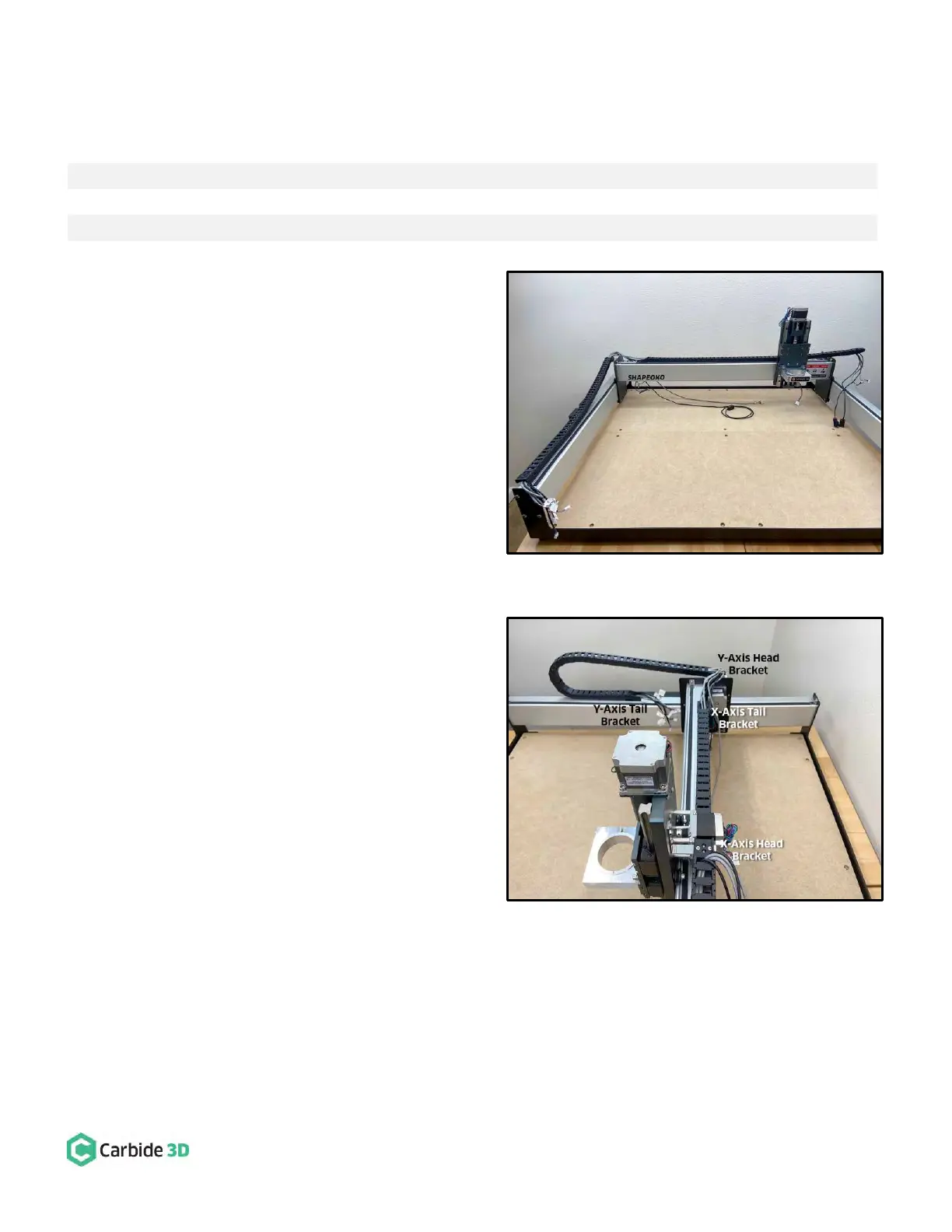
1. Move the X-rail to the back of the machine.
2. Lay the drag chain on the rails. See Fig. 35.
a. First, place the three cables not threaded
through the X-Axis drag chain (Y-Axis
proximity switch and Y1- and Y2-motor
leads) over and behind the X-rail.
b. Second, lift the drag chain and place it
across the Y1- and X-rails.
c. Lay the drag chains so that the tail of the
Y-Axis drag chain will curl under and the
head of the X-Axis drag chain will curl up.
3. Secure the drag chain to the rails. See Fig. 36.
a. Secure the Y-Axis drag chain head to the
head bracket on the outside of the
Y1-carriage.
i. Use a 2mm hex key, needle nose
pliers, two (2) M3×8mm FHS, and
two (2) nyloc nuts to secure.
b. Secure the tail of the Y-Axis drag chain to
the tail plate next to the enclosure.
i. Curl the tail of the drag chain
under and toward the enclosure.
ii. Use a 2mm hex key and one (1)
M3×6mm FHS to secure.
c. Secure the tail of the X-Axis drag chain to
the tail plate near the Y1-motor.
i. Use a 2mm hex key and one (1)
M3×6mm FHS to secure.
d. Secure the head of the X-Axis drag chain to the head bracket on the rear of the HDZ.
i. Curl the head of the drag chain up and toward the HDZ.
ii. Use a 2mm hex key, needle nose pliers, two (2) M3×8mm FHS, and two (2) nyloc nuts to
secure.