support@carbide3d.com docs.carbide3d.com 10/02/2020 Version 1.0
Remove the Homing Switches and Drag Chain
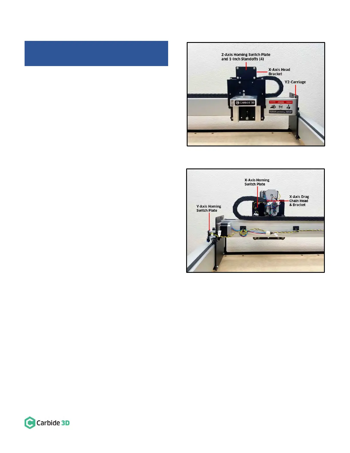
See Fig. 2 (front) and Fig. 3 (back).
1. Disconnect the drag chain from the X-Axis head
bracket on the rear of the X/Z-carriage.
a. Use a 2mm hex key and needle nose pliers
to remove the two (2) M3×8mm FHS and
two (2) nyloc nuts securing the drag chain
to the bracket.
2. Remove the Z-Axis homing switch mounting plate
from the front of the X/Z-carriage, as well as the
four (4) 1-inch standoffs and the X-Axis head
bracket behind the plate.
a. Use a 3mm hex key to remove the four (4)
M5×10mm BHCS securing the plate. (No
need to separate any of the switches from
their mounting plates.)
b. Use a 3mm hex key to remove the four (4)
M5×10mm BHCS securing the four (4)
1-inch standoffs and the head bracket.
c. Set the X-Axis head bracket aside for
re-installation in a later step.
3. Remove the X-Axis homing switch mounting plate
from the rear of the X/Z-carriage.
a. Use a 4mm hex key to remove the two (2)
M5×35mm SHCS, two (2) 1-inch spacers,
and the mounting plate.
4. Remove the Y-Axis homing switch mounting plate from the outside of the Y2-carriage.
a. Use a 4mm hex key to remove the two (2) M5×35mm SHCS, two (2) 1-inch spacers, and the mounting
plate.
5. Disconnect the drag chain from the Y-Axis head bracket on the outside of the Y1-carriage.
a. Use a 2mm hex key and needle nose pliers to remove the two (2) M3×8mm FHS and two (2) nyloc
nuts.
Shapeoko 3 Machines: Skip steps 1, 5, and 6 in this
section.