COMPASS Installation Manual Carefree of Colorado
8 070035-001r1
If installing the BT12 Wireless Awning Control System use the wiring and setup instructions
in “070029-001 BT12 Installation Manual”.
Manual is available on-line at www.carefreeofcolorado.com/carefreeconnects.
AWNING CONTROL SWITCH
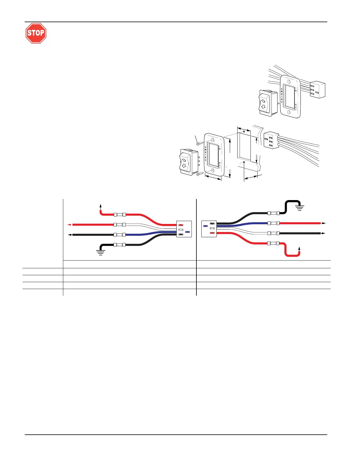
1. At the switch location, cut a rectangular hole 1.25" [3.2cm] x 1.88" [4.8cm].
2. Determine the switch orientation:
2.1. The wires of the connector extend from the
side of the switch with 3 terminals on the
back.
2.2. For wire routing on the right side of the
switch as shown orient the switch with the 3
terminals on the right.
2.3. For wire routing on the left side of the switch
as shown in Detail C, orient the switch with
the 3 terminals on the left.
2.4. Push the switch into the faceplate until the
tabs on the switch “click” into place behind
the faceplate. Ensure that the switch and
faceplate are oriented so that the lettering is
up and the wires are oriented as desired.
2.5. Set switch aside.
3. Route the awning motor wires through the switch hole and attach to the switch connector:
C
ONNECTOR
WIRE COLOR LH CONNECTOR ORIENTATION RH CONNECTOR ORIENTATION
RED→
+12VDC +12VDC
WHITE→
RED (motor wire) BLACK (motor wire)
BLUE→
BLACK (motor wire) RED (motor wire)
BLACK→
Ground Ground
4. Run a minimum 14 awg wire from the power distribution panel (auxiliary battery circuit) or equivalent.
The circuit should be protected by a 15-amp fuse.
5. Run a minimum 14 awg wire to system ground.
NOTE: If the wire run is 30 feet or longer, use 12awg wire to prevent voltage drop.
6. Route the two wires through the mounting hole. Butt splice the 12VDC wire to the R
ED connector wire.
Butt splice the ground wire to the B
LACK connector wire.
7. Attach the connector to the switch.
8. Restore power and test the switch operation. If the awning operates opposite to the switch plate markings:
Shut off power;
Reverse motor wires connected to the blue and white connector wires;
Restore power and test.
9. Push the wires, connector and switch into the mounting hole and secure the switch plate. Use two (2)
#6 x 3/4" flat head screws.
SK003a
To Ground
To +12VDC
BLACK Motor Wire
RED Motor Wire
RED
BLACK
WHITE
BLUE
SK003d
To Ground
To +12VDC
BLACK Motor Wire
RED Motor Wire
RED
BLACK
WHITE
BLUE
SK002d
1.25"
[3.2cm]
1.88" [4
.8cm]
#6 x 3/4 Screw
(2 plcs)
1.88"
[4.8cm]
2
.88"
[7.3cm]
(ref)
1.25"
[3.2cm]
Min. Clearance From Mounting
Face to Rear of Connector
Left Side Orientaion