26
C1
NO1
NO2
NO3
C1
C4
NO4
NO5
NO6
C4
C7
NO7
C7
NO8
C8
NC8
G
G0
U1
U2
U3
GND
+VDC
U4
GND
U5
GND
VG
VG0
Y1
Y2
Y3
Y4
ID1
ID2
ID3
ID4
ID5
ID6
ID7
ID8
IDC1
J1
J2
J3
J4
J5
J14
J10
J13
J12
J15
drac SMBdrac suBdleiF
4321
Tx/Rx
J11 pLAN
GND
J25 BMS2
Tx/Rx
GND
Tx/Rx
GND
J26 FBus2
+Vterm
GND
+5VREF
J24
+
XXXXXXXXXXXX
A
B
CD
NO12
C12
NC12
NO13
C13
NC13
C9
NO9
NO10
NO11
C9
U6
U7
U8
GND
J8
J16
J17
J18
J6
3
8
9
22
24
20
21
J27
1
3
2
4
J28
1
3
2
4
driver
VBAT
G0
G
J30
23
GND
VREF
S1
S2
S3
S4
DI1
DI2
J29
BUILT - IN DRIVER
ID13H
ID13
IDC3
ID14
ID14H
ID9
ID10
ID11
ID12
IDC9
J7
15
26
25
18
17
12
1327 14
Mac address
15
16
10
11
4
5
1
6
2
3 3 7
8
28
ENG
c.pCO sistema +0300057EN rel. 1.2 - 29.05.2017
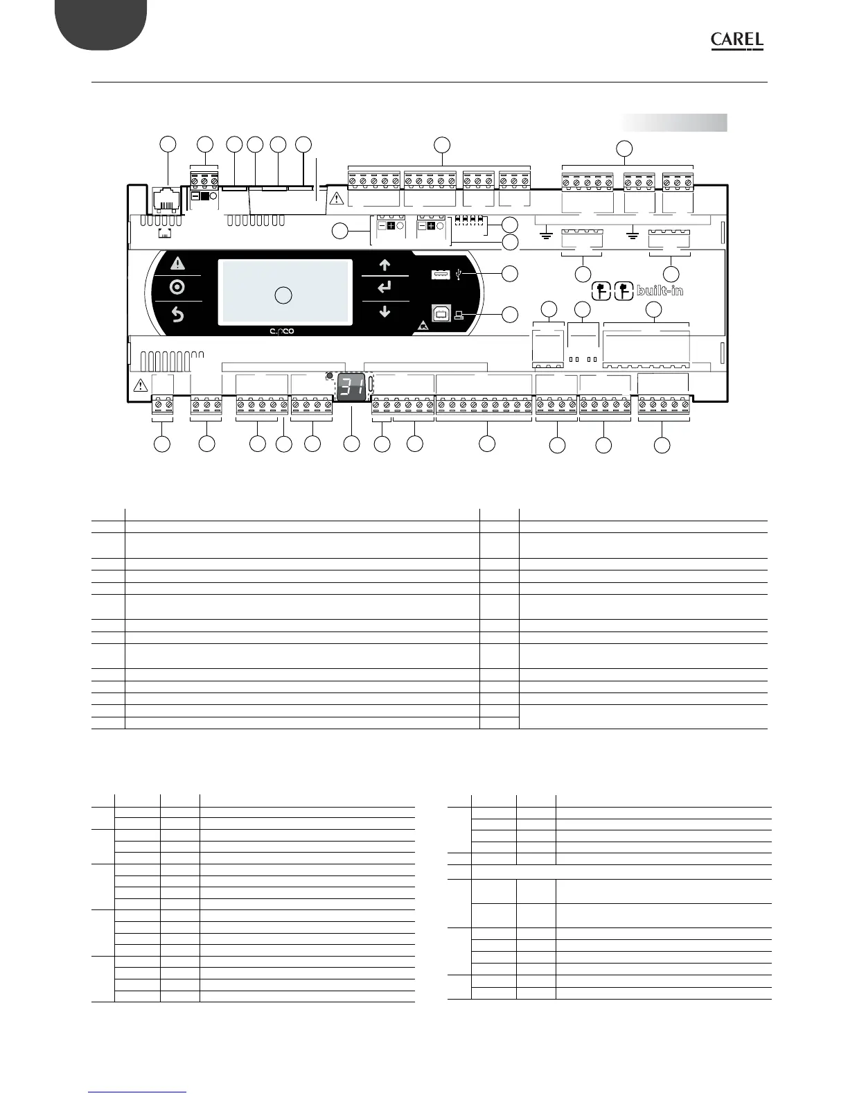
4.2 c.pCO built-in driver: connection terminals
Two models of c.pCO are available with one or two built-in electronic expansion valve drivers.
Fig. 4.w
Key:
Ref. Description Ref. Description
1 Power connctor G(+), G0(-) 15 Relay digital outputs
2
+Vterm: power supply for additional terminal
+5 VREF power supply for ratiometric probes
16 BMS2 port
3 Universal inputs/outputs 17 FieldBus2 port
4 +VDC: power supply for active probes 18 Jumpers for selecting FieldBus/ BMS
5 Button for setting pLAN address, second display, LED 20 Electronic valve A connector
6
VG: power supply at voltage A(*) for opto-isolated analogue output
VG0: power to optically-isolated analogue output, 0 Vac/Vdc
21 Electronic valve B connector
7 Analogue outputs 22 Connector for external Ultracap module (accessory)
8 ID: digital inputs for voltage A (*) 23 Valve driver analogue and digital inputs
9
ID..: digital inputs for voltage A (*)
IDH..: digital inputs for voltage B (**)
24 Valve status indicator LED
10 pLAN telephone connector for terminal 25 USB Host Port (Master)
11 pLAN plug-in connector 26 USB Device Port (Slave)
12 Reserved 27 Faston for earth connection to Ethernet Port
13 Ethernet port 1 28 Display built-in and keypad
14 Ethernet port 2
(*) Voltage A: 24 Vac or 28-36 Vdc; (**) Voltage B: 230 Vac - 50/60 Hz.
Description of connection terminals on c.pCO Small... Extralarge
Ref. Term. Label Description
1
J1-1 G Power supply at voltage A(*)
J1-2 G0 Power supply reference
2
J24-1 +Vterm Additional power supply terminal
J24-2 GND Power supply common
J24-3 +5 V
REF Power supply ratiometric probes 0 to 5 V
3
J2-1 U1 Universal input/output 1
J2-2 U2 Universal input/output 2
J2-3 U3 Universal input/output 3
J2-4 GND Common for universal inputs/outputs 1, 2, 3
3
J3-1 U4 Universal input/output 4
J3-2 GND Common for universal input/output 4
J3-3 U5 Universal input/output 5
J3-4 GND Common for universal input/output 5
3
J6-1 U6 Universal input/output 6
J6-2 U7 Universal input/output 7
J6-3 U8 Universal input/output 8
J6-4 GND Common for universal inputs/outputs 6, 7, 8
Ref. Term. Label Description
3
J20-3i U9 Universal input/output 9
J20-4i GND Common for universal input/output 9
J20-5i U10 Universal input/output 10
J20-6i GND Common for universal input/output 10
4 J2-5 +VDC Power to active probes
5 Button for setting pLAN address, secondary display, LED
6
J4-1 VG
Power to optically-isolated analogue output,
voltage A(*)
J4-2 VG0
Power to optically-isolated analogue output, 0
Vac/Vdc
7
J4-3 Y1 Analogue output 1, 0 to 10 V
J4-4 Y2 Analogue output 2, 0 to 10 V
J4-5 Y3 Analogue output 3, 0 to 10 V
J4-6 Y4 Analogue output 4, 0 to 10 V
7
J20-1i Y5 Analogue output 5, 0 to 10 V
J20-2i Y6 Analogue output 6, 0 to 10 V
 Loading...


