27
ENG
c.pCO sistema +0300057EN rel. 1.2 - 29.05.2017
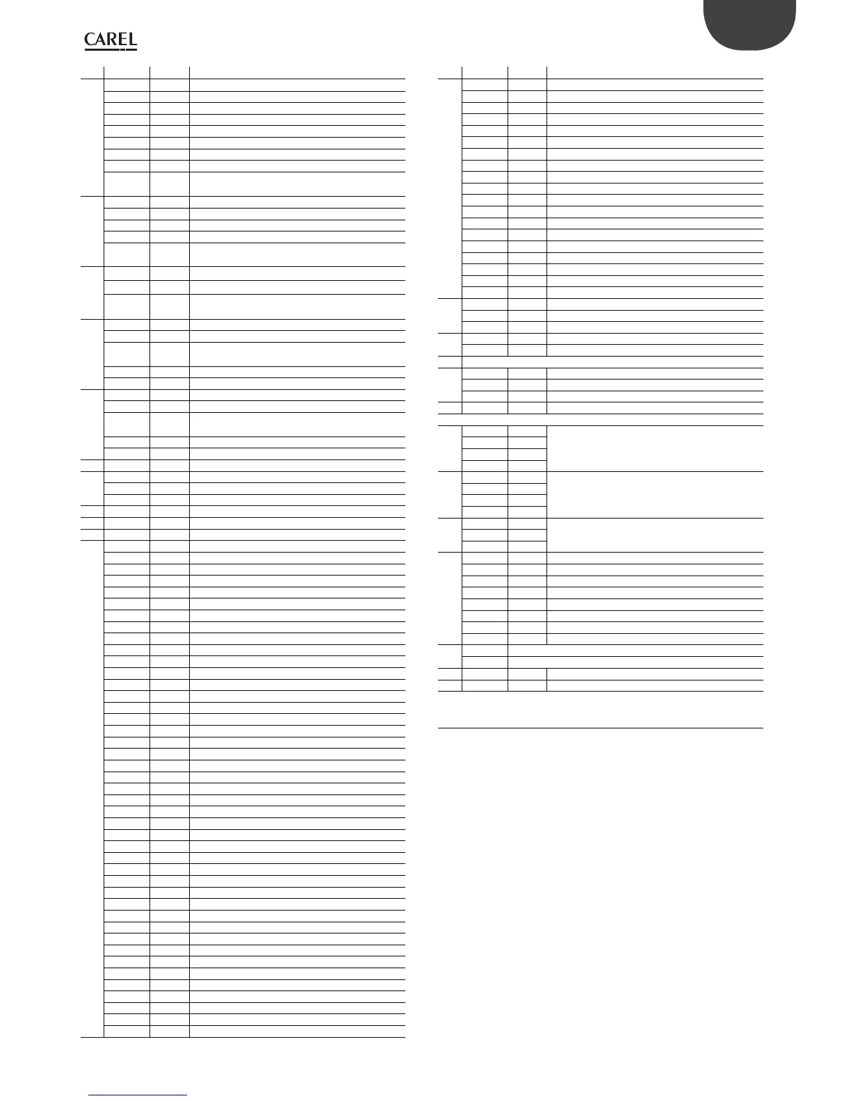
Ref. Term. Label Description
8
J5-1 ID1 Digital input 1 at voltage A(*)
J5-2 ID2 Digital input 2 at voltage A(*)
J5-3 ID3 Digital input 3 at voltage A(*)
J5-4 ID4 Digital input 4 at voltage A(*)
J5-5 ID5 Digital input 5 at voltage A(*)
J5-6 ID6 Digital input 6 at voltage A(*)
J5-7 ID7 Digital input 7 at voltage A(*)
J5-8 ID8 Digital input 8 at voltage A(*)
J5-9 IDC1
Common for digital inputs from 1 to 8 (negative
pole for DC power supply)
8
J7-1 ID9 Digital input 9 at voltage A(*)
J7-2 ID10 Digital input 10 at voltage A(*)
J7-3 ID11 Digital input 11 at voltage A(*)
J7-4 ID12 Digital input 12 at voltage A(*)
J7-5 IDC9
Common for digital inputs from 9 to 12 (negative
pole for DC power supply
8
J20-7i ID17 Digital input 17 at voltage A(*)
J20-8 i ID18 Digital input 18 at voltage A(*)
J20-9i IDC17
Common for digital inputs 17 and 18 (negative
pole for DC power supply
9
J8-1 ID13H Digital input 13 at voltage B(**)
J8-2 ID13 Digital input 13 at voltage A(*)
J8-3 IDC13
Common for digital inputs 13 and 14 (negative
pole for DC power supply)
J8-4 ID14 Digital input 14 at voltage A(*)
J8-5 ID14H Digital input 14 at voltage B(**)
9
J19-1i ID15H Digital input 15 at voltage B(**)
J19-2i ID15 Digital input 15 at voltage A(*)
J19-3i IDC15
Common for digital inputs 15 and 16 (negative
pole for DC power supply)
J19-4i ID16 Digital input 16 at voltage A(*)
J19-5i ID16H Digital input 16 at voltage B(**)
10 J10 - Connector for telephone cable pLAN
11
J11-1 Tx-/Rx- pLAN RS485 port Tx-/Rx-
J11-2 Tx+/Rx+ pLAN RS485 port Tx+/Rx+
J11-3 GND pLAN RS485 port GND
12 - - Reserved
13 - - Ethernet port 1
14 - - Ethernet port 2
15
J12-1 C1 Common for relays 1, 2, 3
J12-2 NO1 Normally open contact, relay 1
J12-3 NO2 Normally open contact, relay 2
J12-4 NO3 Normally open contact, relay 3
J12-5 C1 Common for relay 1, 2, 3
J13-1 C4 Common for relay 4, 5, 6
J13-2 NO4 Normally open contact, relay 4
J13-3 NO5 Normally open contact, relay 5
J13-4 NO6 Normally open contact, relay 6
J13-5 C4 Common for relay 4, 5, 6
J14-1 C7 Common for relay 7
J14-2 NO7 Normally open contact, relay 7
J14-3 C7 Common for relay 7
J15-1 NO8 Normally open contact, relay 8
J15-2 C8 Common for relay 8
J15-3 NC8 Normally closed contact 8
J16-1 C9 Common for relay 9, 10, 11
J16-2 NO9 Normally open contact, relay 9
J16-3 NO10 Normally open contact, relay 10
J16-4 NO11 Normally open contact, relay 11
J16-5 C9 Common for relay 9, 10, 11
J17-1 NO12 Normally open contact, relay 12
J17-2 C12 Common for relay 12
J17-3 NC12 Normally closed contact 12
J18-1 NO13 Normally open contact, relay 13
J18-2 C13 Common for relay 13
J18-3 NC13 Normally closed contact 13
J21-1i NO14 Normally open contact, relay 14
J21-2i C14 Common for relay 14
J21-3i NC14 Normally closed contact 14
J21-4i NO15 Normally open contact, relay 15
J21-5i C15 Common for relay 15
J21-6i NC15 Normally closed contact 15
J22-1i C16 Common for relay 16, 17, 18
J22-2i NO16 Normally open contact, relay 16
J22-3i NO17 Normally open contact, relay 17
J22-4i NO18 Normally closed contact 18
J22-5i
C16 Common for relay 16, 17, 18
J21-1ii C14 Common for relay 14, 15, 16
J21-2ii NO14 Normally open contact, relay 14
J21-3ii NO15 Normally open contact, relay 15
J21-4ii NO16 Normally open contact, relay 16
J21-5ii C14 Common for relay 14, 15, 16
Ref. Term. Label Description
15
J22-1ii C17 Common for relay 17, 18, 19, 20
J22-2ii NO17 Normally open contact, relay 17
J22-3ii NO18 Normally open contact, relay 18
J22-4ii NO19 Normally open contact, relay 19
J22-5ii NO20 Normally open contact, relay 20
J22-6ii C17 Common for relay 17, 18, 19, 20
J19-1ii C21 Common for relay 21, 22, 23, 24
J19-2ii NO21 Normally open contact, relay 21
J19-3ii NO22 Normally open contact, relay 22
J19-4ii NO23 Normally open contact, relay 23
J19-5ii NO24 Normally open contact, relay 24
J19-6ii C21 Common for relay 21, 22, 23, 24
J20-1ii C25 Common for relay 25, 26, 27, 28, 29
J20-2ii NO25 Normally open contact, relay 25
J20-3ii NO26 Normally open contact, relay 26
J20-4ii NO27 Normally open contact, relay 27
J20-5ii NO28 Normally open contact, relay 28
J20-6ii NO29 Normally open contact, relay 29
J20-7ii C25 Common for relay 25, 26, 27, 28, 29
16
J25-1 Tx-/Rx- Tx-/Rx- RS485 BMS2 port
J25-2 Tx+/Rx+ Tx+/Rx+ RS485 BMS2 port
J25-3 GND GND RS485 BMS2 port
17
J26-1 Tx-/Rx- Tx-/Rx- RS485 Fieldbus 2 port
J26-2 Tx+/Rx+ Tx+/Rx+ RS485 Fieldbus 2 port
18 Port J26 conguration microswitches
19
J23-1 Tx-/Rx- Tx-/Rx- Fieldbus 2 RS485 port
J23-2 Tx+/Rx+ Tx+/Rx+ Fieldbus 2 RS485 port
J23-3 GND GND RS485 port network Fieldbus 2
For pCO5+ built-in driver only:
20
J27-1 1
Electronic expansion valve 1 control (see par.
“Electronic valve connection”).
J27-2 3
J27-3 2
J27-4 4
21
J28-1 1
Electronic expansion valve 2 control (see par.
“Electronic valve connection”).
J28-2 3
J28-3 2
J28-4 4
22
J30-1 VBAT
Power supply from external Ultracap moduleJ30-2 G0
J30-3 G
23
J29-1 GND Common probe power supply
J29-2 VREF Probe driver power supply
J29-3 S1 Probe 1
J29-4 S2 Probe 2
J29-5 S3 Probe 3
J29-6 S4 Probe 4
J29-7 DI1 Digital input 1
J29-8 DI2 Digital input 2
24
A, B Valve A status LED
C, D Valve B status LED
Tab. 4.c
(*): voltage A: 24 Vac or 28...36 Vdc;
(**): voltage B: 230 Vac - 50/60 Hz.
i: Large model; ii: Extralarge model
 Loading...


