69
120 Vac
250 Vac 30 Vdc
AC 120 V cosø =0.7
AC 250 V cosø =0.7
250 Vac cosø =0.4
30 Vdc
120 Vac cosø =0.4
30 Vdc
300
200
100
50
30
20
10
5
3
2
1
012345
ENGLISH
µC
2
SE - +030220426 - rel. 2.1 - 09.06.2010
Description Code
µC
2
SE single circuit, 2 compressors, panel mounting MCH2001030
µC
2
SE single circuit, 2 compressors, panel mounting (20 pcs. multiple package) MCH2001031
µC
2
SE
expansion board for 2nd. circuit maximum 4 compressors MCH2000020
µC
2
SE
expansion board for 2nd. circuit maximum 4 compressors (10 pcs. multiple
package)
MCH2000021
RS485 optional board for µC
2
SE panel version MCH2004850
Programming key for µC
2
SE PSOPZKEY00
ON/OFF fan card (only screw terminals) CONVONOFF0
PWM - 0 to 10 V fan card (only screw terminals) CONV0/10A0
Temperature probes for regulation or condensation control
***depending on the length (015= 1.5 m, 030= 3 m, 060=6 m)
NTC***WP00
Pressure probes for condensing pressure control
** depending on the pressure (13= 150 PSI, 23= 75 PSI, 33= 500 PSI)
SPK*R*
Connectors kit for code MCH2000001 (multiple package 20 pcs) MCH2CON001
Connectors kit for code MCH2000001 (multiple package 10 pcs) MCH2CON021
Mini t connectors kit + 1 meter length for code MCH2** MCHSMLCAB0
Mini t connectors kit + 2 meter length for code MCH2** MCHSMLCAB2
Mini t connectors kit + 3 meter length for code MCH2** MCHSMLCAB3
Remote terminal for MCH20000** for panel installation MCH200TP0* MCH200TP0*
Remote terminal for MCH20000** for wall-mounting MCH200TW0* MCH200TW0*
Supervisor serial connection kit for remote terminal MCH200TSV0
Fan speed PWM 4 A/230 Vac MCHRTF04C0
Fan speed PWM 8 A/230 Vac MCHRTF08C0
Fan speed PWM 12 A/230 Vac MCHRTF12C0
Fan speed PWM 10 A/230 Vac 1 Pc. Nor. Ind. MCHRTF10C0
Fan speed PWM 10 A/230 Vac 10 Pc. Nor. Ind. MCHRTF10C1
Table 9.a
10. TECHNICAL SPECIFICATIONS AND SOFTWARE UPDATES
10.1 Technical speci cations
Electrical speci cations
In the following speci cations “Group A” de nes the grouping of the following outputs: valve,
pump, compressor, heater.
Power supply 24 Vac, range +10/–15 %; 50/60 Hz
Maximum power input: 3W
Fuse (compulsory) in series with the power supply to the µC
2
SE: 315mAT
12 pin connector Max. current 2 A for each relay output, extendable to 3 A for one single
output
Relays Max current at 250 Vac: EN60730: resistive: 3A, Inductive: 2A cos =0.4
60,000 cycles
UL: Resistive: 3A, 1 FLA, 6 LRA cos =0.4 30,000 cycles
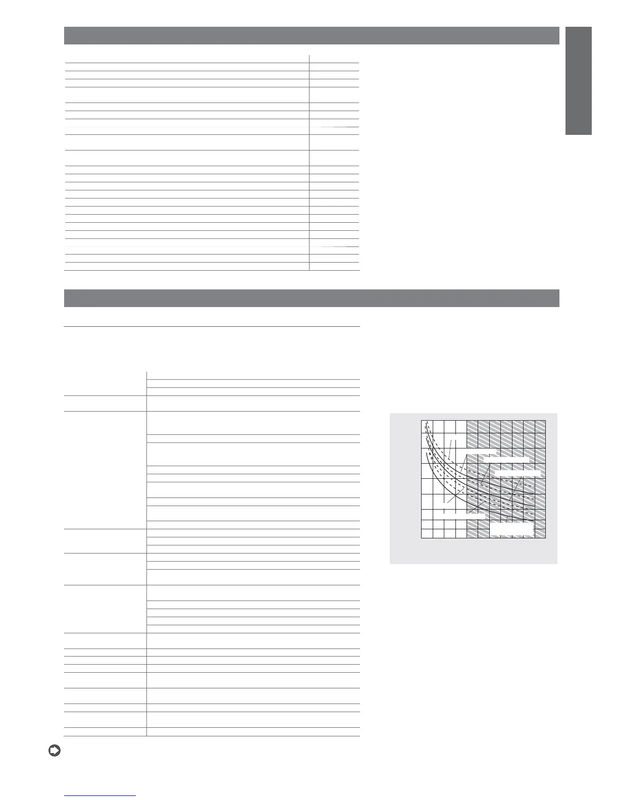
For further information refer to the characteristics shown in Figure 10.a
Minimum interval between communications (each relay): 12 s (the
manufacturer of the unit that the device is integrated into must ensure
the correct con guration so as to respond to this speci cation
Type of microswitching: 1 C
Insulation between relays in group A: functional
Insulation between the relays in group A and the very low voltage parts:
reinforced
Insulation between relays in group A and the signal relays: primary
Insulation between the signal relays and the very low voltage parts:
reinforced
Insulation between the relays and the front panel: reinforced
Digital inputs Electrical standard: voltage-free contacts
Closing current to earth: 5 mA
Maximum closing resistance: 50 W
Analogue inputs B1, B2, B3, B4: NTC CAREL temperature probes (10 kW at 25 °C)
The response time depends on the component used, typical value 90 s
B4: NTC temp. probes (10 kW at 25 °C) or CAREL 0 to 5 V ratiometric
pressure probes SPKT00**R*
Fan output Control signal for CAREL modules MCHRTF****, CONVONOFF* and
CONV0/10A*
Phase width modulation (settable width) or modulation of the duty cycle
No-load voltage: 5V ± 10%
Short-circuit current: 30 mA
Minimum output load: 1 kW
Front panel index of
protection
IP55
Storage conditions -10T70 °C – humidity 80 % rH non-condensing
Operating conditions -10T55 °C – humidity <90 % rH non-condensing
Degree of pollution Normal
Cat. of resist. to heat and
r e
D (RU94 V0)
PTI of the insulating
materials
All the insulating materials have PTI250 V
Software class and structure A
Period of electric stress
across insulating parts
Long
Homologations CE/RU (File EI98839 sez.16)
Table10.a
Nota: all the relays must have the common terminals (C1/2, C3/4, C6/7, C8/9) connected
together.
Fig. 10.a
current on contacts (A)
number of operations (x 10
4
)

 Loading...