Parametri interessanti
(*) compaiono solo se è presente la scheda opzionale CR72SER
C01=1.C Termostato, pressostato, umidostato ... con Set-Point centrale
Questo modo di funzionamento è del tutto analogo al precedente (C01=1);
l'unica eccezione è dovuta al fatto che il differenziale è posto centralmente
rispetto al Set-Point. Il Set-Point quindi, non è più il valore che determina
lo spegnimento degli attuatori, ma rappresenta il valore medio ottenuto
dalla regolazione. In direct l'uscita OUT1 è attivata quando la grandezza
controllata supera il valore SET1; è attivata anche l'uscita OUT2 quando
la grandezza supera il valore SET1+1/2 P01. Le uscite vengono disattivate
quando la grandezza controllata scende sotto il valore SET1 (OUT2) e
SET-1/2P01 (OUT). In reverse l'uscita OUT1 si attiva quando la grandezza
controllata scende sotto il valore SET1 e si attiva anche l'uscita OUT2
se la grandezza scende sotto il valore SET1-1/2P01. Le uscite vengo-
no disattivate quando la grandezza controllata risale al valore SET1
(OUT2) e SET1+1/2P01 (OUT1) (*). P01 è globale per entrambe le
uscite che lo suddividono in due parti uguali.
(*) con la rotazione abilitata (vedere parametro C04), l'ordine di
attivazione e di spegnimento fra le due uscite può essere scambiato
Parametri: sono gli stessi visti per C01=1, cambia solamente C01=1.C
C01 = 1.A Funzionamento con uscita di allarme
Questo modo di funzionamento fissa l'uscita OUT1 con logica del tutto
analoga a quella per C01=1 ad una uscita (vedere cap. “configurazione
dei modelli ad 1 uscita - parametro C01=1”) mentre OUT2 gestisce un
comando di allarme generale. Il regolatore attiva immediatamente l'uscita
OUT2 nel caso in cui si presenti un'allarme di alta, bassa o da ingresso
digitale, oppure un allarme interno, di sonda sconnessa o guasta. Per
ulteriori informazioni vedere il capitolo “Allarmi”.
Parametri fondamentali
Per quel che concerne la regolazione attuata da OUT1, sono gli stessi
visti per C01=1 (cap. “Configurazione dei modelli ad 1 uscita - parame-
tro C01=1” ). Per quanto riguarda la gestione allarmi, attuata da OUT2
si rimanda alla descrizione della gestione allarmi trattata al cap. “Allarmi”
e a i parametri P14 e P15 (vedere par. “Descrizione dei parametri operativi”).
Parametri interessanti
(*) compaiono solo se è presente la scheda opzionale CR72SER.
Supplementary parameters
(*) only when optional CR72SER is present
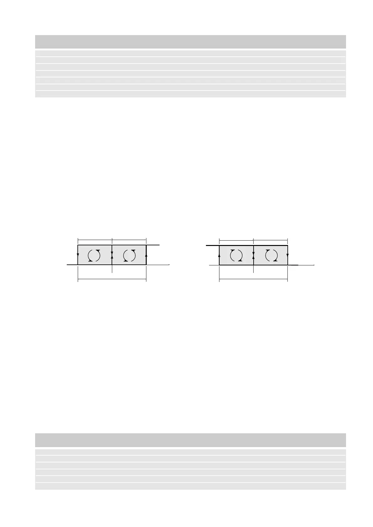
C01=1.C Therm., pressure-stat, humidistat with central Set-Point.
This method of working is similar to the previous one (C01=1), the only
exception being that the differential is placed centrally around the Set-Point.
The Set-Point is therefore no longer the value determining the operation of
the actuators, but rather represents the mean value achieved by the control.
In direct mode, output OUT1 is activated when the measurement being con-
trolled exceeds the value of SET1; OUT2 is activated in addition when the
measurement exceeds SET1+1/2P01.The outputs remain ON until the mea-
surement being controlled falls below the value of SET1 (OUT2) and SET1-
1/2P01 (OUT1). In reverse operation OUT1 is activated when the measu-
rement being controlled falls below the value SET1, and OUT2 is activated in
addition if the measurement being controlled falls below the value of SET1
(OUT1) and SET1-1/2P01.The outputs remain ON until the measurement
being controlled rises to the value of SET1 (OUT2) and SET1+1/2P01
(OUT1)*. P01 is total for the two outputs, which divide it into equal parts.
(*) With rotation set up (see parameter C04), the order of activation and
de-activation between the two outputs can be changed.
Parameters: These are the same as for C01=1, except that C01=1.C.
C01=1.A Operation with an alarm output
This method of operation sets up OUT1 in a way completely analogous
to C01=1 on a one-output unit (par. 5.1), while OUT2 manages a gene-
ral alarm command. The control activates OUT2 immediately if there is
a high or low alarm, a digital input alarm, or an internal alarm concer-
ning a disconnected or faulty probe.
For further information see chapter “Alarms”.
Main parameters
As regards OUT1, these are the same as for C01=1 (par. 5.1).
As regards alarm control activated by OUT2, reference should be
made to the management of alarms dealt with in chapter 11 and to
parameters P14 and P15.
Supplementary parameters
(*) only when optional CR72SER is present
15
Regolazione Allarme Tempistiche protezione Sicurezza Lettura (*) Uscita analogica (*) Indirizzo seriale
Control Alarm Time protection Safety Reading (*) Analog output (*) Serial address
C21 C26 P08 C16 C06 C22 C29
P22 P14 P09 C17 C15 C23
P23 P15 P10 C26 P00 P07
P24 P11 C27 (*) P04
P25 P12
P26 P13
Regolazione Allarme Tempistiche protezione Sicurezza Lettura (*) Uscita analogica (*) Indirizzo seriale
Control Alarm Time protection Safety Reading (*) Analog output (*) Serial address
C04 C26 P08 C16 C06 C22 C29
C21 P14 P09 C17 C15 C23
P22 P15 P10 C18 P00 P07
P23 P11 C19 P04
P24 P25 C27 (*) P12
P26 P13
P27
 Loading...


