Code +030220811- rel. 1.0 – 26.04.2007
14
5.2 Probe and power supply connections
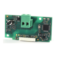
Then complete the wiring of the driver, following the information provided on the instruction sheet supplied in the
packaging.
Connect the 24 V power supply, the optional battery module, the optional communication LAN (pLAN, tLAN or
RS485), the alarm relay, if used, the digital input for enabling control, if used, and finally the temperature and
pressure probes.
• temperature probe
: 2 wires, indifferent polarity;
• ratiometric pressure probe SPKT*R0:
3 wires, earth (green), 5 Vdc power supply (black) and signal (white);
• 4-20mA pressure probe SPKT*C0:
2 wires, 2-28 Vdc power supply (black) and signal (white).
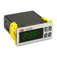
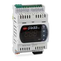
If the driver is used with the RS485 serial or pLAN address setting via hardware (with microswitches, binary logic) as
for the EVD200 and EVD300, refer to the corresponding instruction sheets to set the communication address. To
make the configuration, lift the front panel that houses the signal LEDs and set the position of microswitches from 1
to 5, making sure not to damage the flat connection cable to the main printed circuit.
5.3 Battery module connection (for closing the valve)
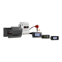
The EVBAT00*00 battery modules are electronic devices that guarantee temporary power supply to the EVD200-
300-400 drivers and the built-in driver on the mpxPRO (chapter 6). Powered by a backup battery, these provide
continuous voltage to the driver for the time required to completely close the electronic valve in the event of
mains power failures
, while during normal operation the module makes sure the battery is recharged.
Battery modules for EVD200 and EVD300:
• EVBAT00100
: complete kit including the power supply/battery charger, 3 x 6V 1.2 Ah batteries and the set of
connection cables, and can supply just one valve.
• EVBATBOX00: support for 3 batteries with DIN rail mounting.
• 6436503AXX: spare battery
Battery modules for EVD400 and mpxPRO:
• EVBAT00300
: complete kit including the power supply/battery charger, 2 x 6V 1.2 Ah batteries and the set of
connection cables, and can supply two valves at the same time.
• EVBATBOX10: support for 2 batteries with DIN rail mounting.
• 6436503AXX: spare battery
• 59C545A003: spare set of connection cables
• EVBAT00200: spare power supply/battery charger module.
Below are the connection diagrams of the two modules to the corresponding drivers and the dimensional drawings
of the battery supports.
Fig. 5.e
Fig. 5.d
Fi
. 5.f
installation
 Loading...