1. Selecting the valve
The electronic expansion valve must be sized based on the cooling capacity of the evaporator it serves.
For the correct selection of the valve, see the "E
2
V– E
4
V valve selection" manual +030220815, downloadable from
www.carel.com. Alternatively, guided selection software is available on ksa.carel.com.
Incorrect sizing may cause various problems.
If the valve is undersized
the performance of the system will be affected, as it will not be possible to reach the
desired temperature and the superheat will generally be high or greater than the set point.
If on the other hand the valve is oversized
, the problems may involve system “swings” (there may be wide
variations in temperature, pressure and superheat), and consequently poor efficiency, or alternatively there may be
the return of liquid to the compressor.
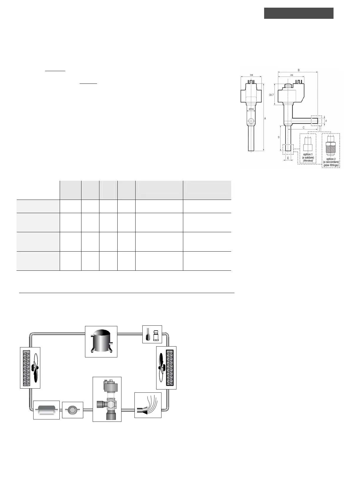
2. Installing the valve
The electronic valve is installed using threaded or braze-welded fittings, depending on the codes:
• E2V***S0** welded with stainless steel end, outside diameter 10 mm.
• E2V***SF** welded with copper end, outside diameter 12 mm.
• E2V***SM** welded with copper end, outside diameter 16 mm.
• E2V***RB** threaded with 3/8” side end, 1/2” longitudinal end.
To the side is the dimensional drawing of the E
2
V valves; the table below shows the dimensions of the various
models.
A
(mm/in
ch)
B
(mm/
inch)
C
(mm/
inch)
D
(mm/
inch)
E
(mm/inch)
F
(mm/inch)
E2V***S0**
Inox/steel/ 10-10
127.0
(5.0)
73.7
(2.90)
54.7
(2.15)
48.5
(1.98)
ID 9 / OD 10
(in 0.35 / ext. 0.39)
ID 9/OD 10
(in 0.35 / ext. 0.39)
E2V***SF**
Rame/copper
12-12 mm ODF
121.9
(4.79)
68.7
(2.70)
49.7
(1.95)
43.4
(1.71)
ID 12.1 / OD 14
(in 0.47 / out. 0.55)
ID 12.1 / OD 14
(in 0.47 / out. 0.55)
E2V***SM**
Rame/copper
16-16 mm ODF
123.9
(4.87)
70.7
(2.78)
51.7
(2.03)
45.4
(1.79)
ID 16.1 / OD 18
(in 0.63 / out. 0.71)
ID 16.1 / OD 18
(in 0.63 / out. 0.71)
E2V***RB**
ottone/brass
3/8”-1/2” SAE
139.9
(5.51)
86.7
(3.41)
67.7
(2.42)
61.4
(2.42)
ID 9/¾” thread
(in 0.35 / 3/4” thread)
ID 9/¾” thread
(in 0.35 / 3/4” thread)
Tab. 2.a
2.1 Diagram of the refrigerant circuit
Below is a typical diagram of the refrigerant circuit, with the components that are always featured and the optional
components, indicating the typical position of the E
2
V valve and the sensors required for the calculation of the
superheat. The sight glass is not strictly necessary, however is useful when seeking the cause of malfunctions. The
solenoid valve is generally used in refrigeration systems (showcases, cold rooms) to stop the flow of refrigerant
when the utility is not cooling.
Valvola di espansione E
4
V
E
4
4 expansion valve
Evaporatore
Evaporator
Condensatore
Condenser
NTC
Misura del surriscaldamento
Superheat detection
Compressore
Compressor
Fig. 2.b
Fi
. 2.a
installation
 Loading...