Code +030220811- rel. 1.0 – 26.04.2007
8
2.2 In-line filter
Always install a mechanical filter before the refrigerant inlet, with both welded valves (E2V***S***) and valves with
threaded fittings (E2V***RB**). For the latter, a filter is supplied inside the packaging that can be placed directly in
the valve inlet pipe.
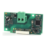
If the installation is bi-directional (flow of refrigerant in both directions, reverse-cycle heat pumps), a bi-directional
liquid/gas filter should be fitted on both expansion valve connections, or other solutions can be used, depending on
the layout of the installation.
2.3
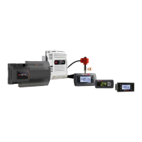
Flow of refrigerant and spatial orientation of the valve
The recommended direction of connection (Figure 2.c) sees the inlet on the side of the valve; nonetheless, the
CAREL E
2
V valves are bi-directional up to the pressure differential specified on the instruction sheet.
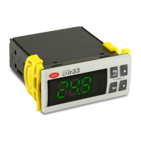
Important: in no circumstances is upside-down installation allowed, that is, with the stator facing downwards.
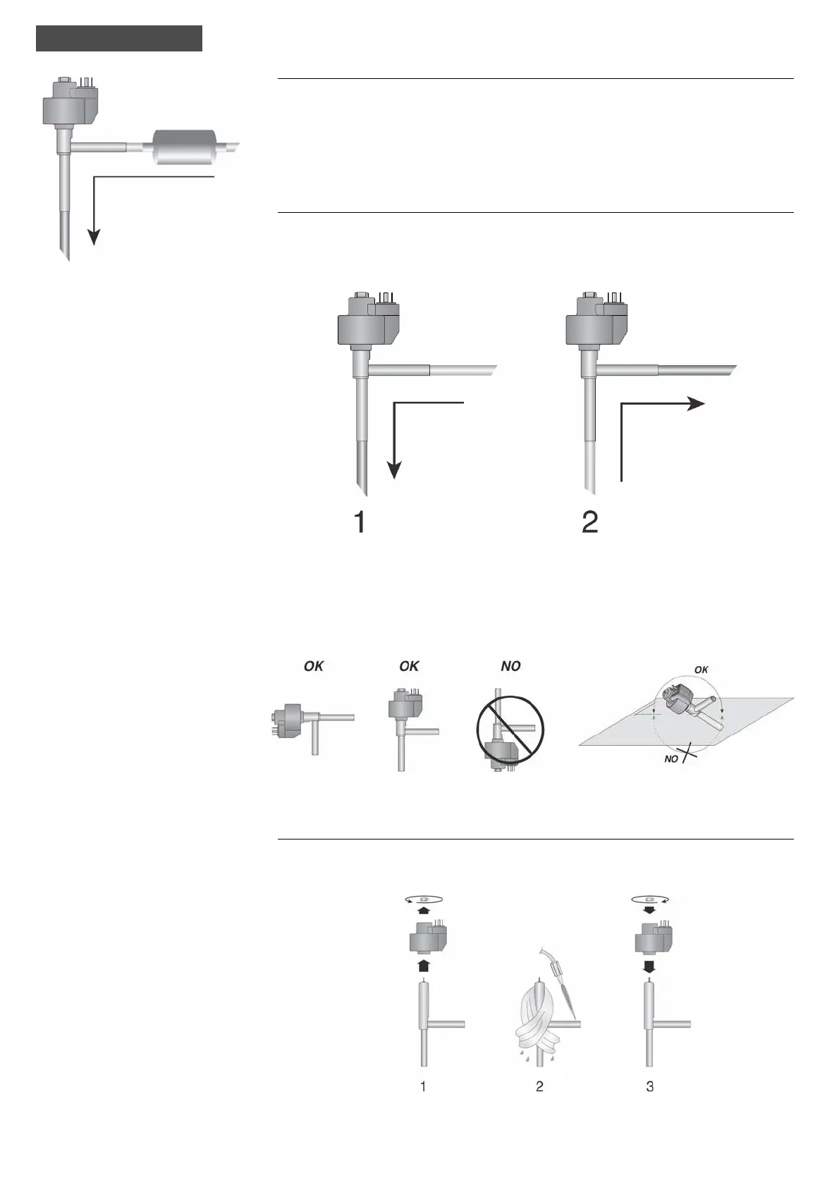
2.4 Welding
Unscrew the locking nut and remove the stator (winding). If necessary, remove the connector if inserted. Before
starting welding, wrap the body of the valve (without the stator)
in a wet rag, to avoid overheating the inside parts.
When finished welding, replace the stator
and tighten the valve-stator locking nut.
Fig. 2.c
Fig. 2.d
Recommended
direction
Fig. 2.e
Fig. 2.f
installation
 Loading...