23
ENG
“EVD evolution” +030222041 - rel. 1.0 - 01.06.2008
S2
S4
S1
EVD
evolution
P
E
V
S
F
L
M
T
T
CP
C
EEV
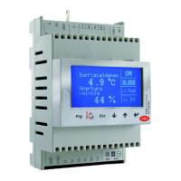
Fig. 5.i
Key:
CP Compressor EEV Electronic expansion valve
C Condenser V Solenoid valve
L Liquid receiver E Evaporator
F Dewatering filter P Pressure sensor (transducer)
S Liquid indicator T Temperature sensor
For the wiring, see paragraph 2.7 “General connection diagram”.
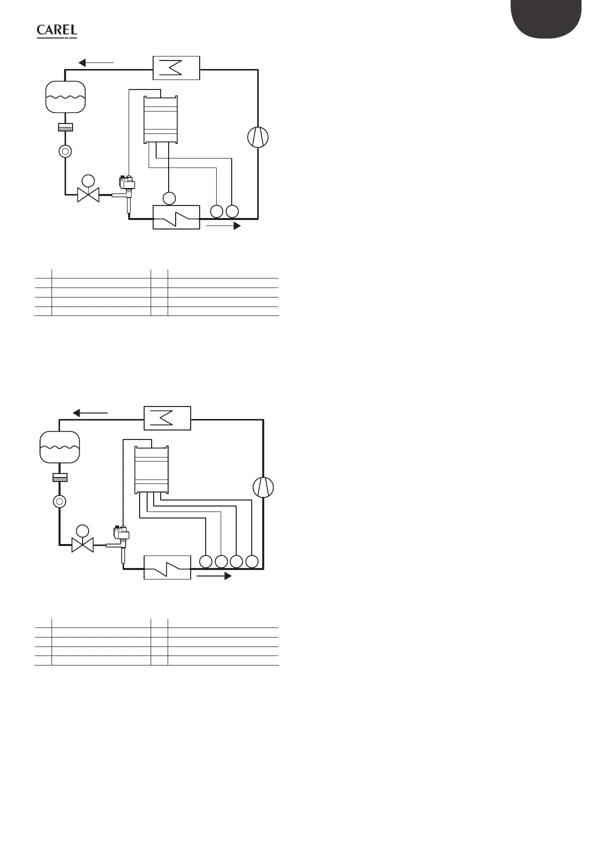
Backup sensors on S3 & S4
In this case, pressure sensor S3 and temperature sensor S4 will be used
to replace sensors S1 and S2 respectively in the event of faults on one or
both, so as to guarantee a high level of reliability of the controlled unit.
S2
S4
S3
S1
EVD
evolution
P
E
V
S
F
L
M
T
P T
CP
C
EEV
Fig. 5.j
Key:
CP Compressor EEV Electronic expansion valve
C Condenser V Solenoid valve
L Liquid receiver E Evaporator
F Dewatering filter P Pressure sensor (transducer)
S Liquid indicator T Temperature sensor
For the wiring, see paragraph 2.7 “General connection diagram”.