FCM electronic regulator Cod. +302235300 - Rel. 2.0 del 30/11/98
1
Contents
1 Introduction........................................................................................................................................................................................ 2
1.1 General characteristics ...................................................................................................................................................................... 2
2 Codes of instruments and accessories................................................................................................................................................ 2
2.1 FCM* codes...................................................................................................................................................................................... 2
2.2 Accessories ....................................................................................................................................................................................... 2
3 Buttons and displayed indications ..................................................................................................................................................... 3
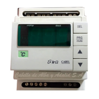
3.1 Front panel........................................................................................................................................................................................ 3
4 Installation.......................................................................................................................................................................................... 4
4.1 Mounting the instrument ................................................................................................................................................................... 4
4.2 Electrical connections........................................................................................................................................................................ 4
5 Functions............................................................................................................................................................................................ 5
5.1 Serial option...................................................................................................................................................................................... 5
6 Programming and configuring the FCM*......................................................................................................................................... 6
6.1 Standard configuration....................................................................................................................................................................... 6
6.2 Initialisation of FCM* instruments .................................................................................................................................................... 6
6.3 Auxiliary functions............................................................................................................................................................................ 7
6.4 High and Low alarms (not available in slave mode)........................................................................................................................... 8
6.5 Defrosting (not available in SLAVE mode)........................................................................................................................................ 8
6.6 Multifunction digital inputs............................................................................................................................................................... 9
6.7 Multi-function digital output............................................................................................................................................................ 10
6.8 Extra LED indicators....................................................................................................................................................................... 10
7 Programming FCM controllers ....................................................................................................................................................... 11
7.1 Setting the set-point ("St" parameters)............................................................................................................................................. 11
7.2 Accessing "P" parameters................................................................................................................................................................ 11
7.3 Accessing "C" parameters................................................................................................................................................................ 11
7.4 Validity of the modifications............................................................................................................................................................ 12
7.5 Displaying the unit of measure ........................................................................................................................................................ 12
7.6 Setting min. and max. output values ................................................................................................................................................ 12
7.7 Factory-set parameters..................................................................................................................................................................... 13
7.8 Remote Control............................................................................................................................................................................... 13
7.9 Technical specifications................................................................................................................................................................... 13
7.10 Description of the keypad .............................................................................................................................................................. 13
7.11 Using the remote control................................................................................................................................................................ 14
7.12 Setting the access code .................................................................................................................................................................. 14
8 Description of the parameters.......................................................................................................................................................... 15
8.1 Parameters concerning the set-point................................................................................................................................................. 15
8.2 Parameters concerning the analogue output...................................................................................................................................... 16
8.3 Parameters concerning inputs .......................................................................................................................................................... 18
8.4 Alarm parameters............................................................................................................................................................................ 19
8.5 Parameters concerning digital inputs and output .............................................................................................................................. 20
8.6 Parameters concerning the unit of measure ...................................................................................................................................... 21
8.7 Parameters concerning defrost ......................................................................................................................................................... 23
8.8 Parameters concerning keypad and remote control ........................................................................................................................... 24
8.9 Parameters concerning serial connection.......................................................................................................................................... 25
9 Table of Parameters......................................................................................................................................................................... 27
10 Alarms ............................................................................................................................................................................................ 31
11 Technical specifications.................................................................................................................................................................. 32
12 Wiring diagram.............................................................................................................................................................................. 33
12.1 Terminal block.............................................................................................................................................................................. 33
12.2 Power supply:................................................................................................................................................................................ 33
12.3 Connecting probes......................................................................................................................................................................... 34
13 Dimensions...................................................................................................................................................................................... 35