10
ENG
Gas Leakage Detector +0300047IE rel 1.1 - 26.04.2023
Installation
2.2.3 Chillers
Measuring leaks on outdoor chillers is generally more di cult, given the highly-variable air ow.
Generally, it is recommended to install the gas detectors near the compressor, as this is the place where refrigerant leaks are most
likely to occur. In particular, check if it is possible to install the gas detector inside the closed unit near the compressor, where gas
is more likely to stagnate. However, avoid vibrating surfaces or surfaces that are di cult to access for maintenance.
It is also recommended to install gas detectors along the ventilation system, especially in the event of low or variable air ow
speeds.
2.2.4 Air conditioning - direct VRF/VRV systems
In air conditioned buildings, it is recommended to install at least one gas detector in each room, identifying the areas of greatest
risk, such as air ows from ventilation systems and heating systems such as radiators.
In these spaces, the refrigerant gas is usually denser than air: consequently, the gas detectors should be installed close to the
oor.
Also consider installing the gas detector in ceilings or false ceilings, if not adequately sealed.
Do not install the gas detectors underneath mirrors/washbasins and inside bathrooms.
Do not install the gas detectors near sources of steam.
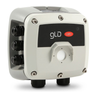
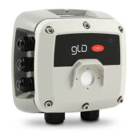
2.3 Installation
Once the optimal position to install the sensor has been chosen, it is recommended to install the sensor (identi able on the
device by the red colour) in a vertical position, with the sensitive element (red part) facing downwards. The sensor can now be
mounted on the wall, as follows:
1. Drill the holes in the wall using the template (at the end of the manual) as a reference.
2. Remove the two top and bottom plastic frames, as shown in the gure
3. Fix the device using four screws, chosen according to the type of installation and the type of wall, maximum diameter 4
mm.
J6
J5
3B
2B
1B
3A
2A
1A
–
+
G
+
B
A
G0
Sh
J2
J1
R1
W3
W2
W1
W8
W7
W6
W5
W4
J7
J8
J4
J3
24 Vac/dc
4. Open the cover of the GLD, t the cable glands and make the required electrical connections. The plug-in terminals can be
removed from the device to facilitate wiring.
 Loading...