Do you have a question about the Carel GLD Small Series and is the answer not in the manual?
Information on proper disposal of electrical and electronic equipment according to WEEE directive.
Warning to separate power and signal cables to avoid electromagnetic disturbance.
Explanation of symbols used in the manual for warnings and notices.
Guidelines for food safety programs and periodic checks of measurement devices.
Details on the intended uses and applications of the GLD Small series leakage detectors.
Warnings regarding semiconductor sensors detecting other gases and potential false alarms.
Warnings against use in oxygen-enriched or hazardous locations (ATEX, NFPA).
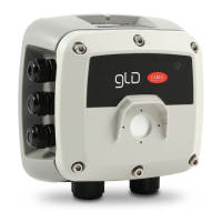
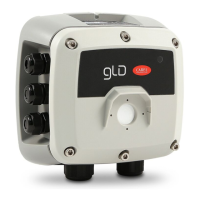
Overview of the different versions available for the GLD Small series.
Illustrations and measurements for both built-in and remote versions of the device.
Key aspects to consider for proper installation of the gas detector.
Guidelines for positioning detectors in equipment rooms based on gas characteristics.
Recommendations for installing detectors in cold rooms, considering airflow and evaporator location.
Recommendations for installing detectors in chillers, near compressors and ventilation systems.
Guidelines for positioning detectors in air-conditioned buildings with VRF/VRV systems.
Step-by-step guide for mounting the device and making electrical connections.
Important notes regarding power supply, wiring, and RFI immunity regulations.
Description of the start-up and warm-up phases of the device.
Visual indications of device operating status using LEDs and relay outputs.
Guide to configuring device parameters using the internal rotary switch and a voltmeter.
Explanation of the function of each LED on the rotary switch for parameter setting.
Details on the configurable analogue output signal and its relation to gas concentration.
Information on alarm activation thresholds and default set points for different gas groups.
How to use the magnetic key for Bluetooth activation and alarm acknowledgement.
Steps to connect the GLD Small to the RILEVA TE app using Bluetooth.
Verifying Bluetooth connection status on the app and device.
Displaying current concentration and accessing other app functions from the home screen.
Viewing and modifying sensor parameters, gas type, and other settings via the app.
Configuring Modbus parameters like address, baud rate, and parity via the app.
Activating test mode for debugging functions like relay and LED tests.
Accessing app settings, device info, reports, and legal information.
Recommendations for using shielded cables and ensuring optimal serial network operation.
Table of Modbus parameters and their default values for app or rotary switch configuration.
List of Modbus input registers for reading device status and measurements.
Modbus registers for writing configuration and control commands to the device.
List of Modbus input registers for reading device status and measurements.
Modbus coils for writing specific commands and reading simple status flags.
Explanation of operating timers like MaxDaysOnLine and MaxDaysToService.
Procedure for calibrating the device using a known gas concentration and calibration kit.
Description of the calibration kit components and how to connect them for calibration.
Step-by-step guide for performing calibration using the RILEVA TE mobile application.
Reviewing calibration data and entering environmental conditions for the report.
Saving the calibration report and verifying completion by checking updated calibration dates.
Flowchart illustrating the steps involved in zero and span calibration via Modbus.
Detailed explanation of register operations for performing zero and span calibration.
Step-by-step guide for replacing the sensor in the built-in version of the detector.
Step-by-step guide for replacing the sensor in the remote version of the detector.
Explanation of how semiconductor, infrared, and electrochemical sensors detect gases.
Information on pre-calibrated sensors and devices supplied with calibration certificates.
Table listing detected gases, their groups, technology, default gas, and calibration gas.
Behavior of warning and alarm relays during the initial power-on sequence.
Explanation of the two relay operating modes: failsafe and warning fault.
Description and wiring diagrams for the default failsafe mode of the relays.
Explanation of the Warning Fault mode for relays and its configuration.
Guidelines for disposing of the device according to WEEE regulations.
Instructions for disposing of sensors in accordance with local laws and safety warnings.
List of part numbers for the GLD Small series gas detectors and their descriptions.
List of part numbers for the replaceable sensitive elements and their descriptions.
List of available accessories, including the calibration kit.
Categorization of gases detected by semiconductor versions of the GLD Small.
| IP protection | IP42 |
|---|---|
| Housing Material | ABS |
| Operating temperature | -10 to +50 °C |
| Response time | < 30 s |
| Measurement Range | 0…100% LEL |
| Output Signal | 4-20 mA |
| Storage temperature | -20 to +60 °C |