13
ENG
Gas Leakage Detector +0300047IE rel 1.1 - 26.04.2023
Operation
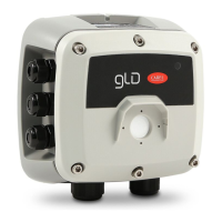
Fig. 3.a
The basic conguration can be performed using the rotary switch, following the instructions described below. To complete the
conguration, a digital multimeter is required, with the test leads connected to connector J6. In this way, the tester will show a
voltage between 0 and 10 Volts, indicating the value selected by the rotary switch. The meaning of the voltage value displayed
changes depending on the selected function: the table below shows the meaning of each voltage for each function.
Setting mode is activated by pressing and holding the rotary switch for 5 seconds. The LED that is ON acts as the menu point,
indicating which parameters will be set (all the other LEDs are OFF). Turn the switch to select the parameter to be set. Reading
the table, the voltage read with a voltmeter connected to the service terminal indicates the chosen setting.
Pressing the rotary switch for 2 seconds accesses the selected parameter. The corresponding LED ashes.
Turning the rotary switch changes the parameter setting.
After having made the setting, pressing the rotary switch for 5 seconds saves the new value.
Turning the rotary switch again moves to the next parameter.
After two minutes of inactivity or using the magnetic latch, the detector returns to normal operating mode.
Description of the rotary switch LEDs
The table below shows the value of the selected parameter and the corresponding voltage value. Each LED corresponds to a
dierent parameter. The default parameter values are saved to permanent memory.
LED W1
Not used
LED W2
Warning level.
The operator can set the warning threshold.
See the table below for the voltage value corresponding to the selected setting.
LED W3
Alarm level
The operator can set the alarm threshold.
See the table below for the voltage value corresponding to the selected setting.
LED W4
Modbus address
The operator can set the Modbus address.
To set the values with greater precision, use the Modbus serial connection or app.
See the table below for the voltage value corresponding to the selected setting.
LED W5
Alarm delay
The operator can select the delay time for activation of the LED and the alarm relay after the alarm threshold has
been exceeded.
See the table below for the voltage value corresponding to the selected setting.
LED W6
Type of analogue output voltage.
The operator can select the type of analogue output.
See the table below for the voltage value corresponding to the selected setting.
LED W7
Alarm/warning reset function mode
This parameter is used to select the warning and alarm reset modes.
0 = manual reset (latch) / 1 = automatic reset
LED W8
Modbus conguration
The operator can choose the desired Modbus conguration from the options available.
See the table below for the voltage value corresponding to the selected setting.
3.3 Setting the device using the rotary switch
The rotary switch is located inside the device, on the electronic board (R1).
J6 J5
3B
2B
1B
3A
2A
1A
–
+
G
+
B
A
G0
Sh
J4
J3
J2
J1
J7
J8
R1
W3
W2
W1
W8
W7
W6
W5
W4
24 Vac/dc
 Loading...