18
Fig. 6.a
Fig. 6.b
ENGLISH
µAD +030220465 - rel. 1.1 - 15.12.2010
Ht01: Differential temperature
Set the temperature adjustment differential, Range: 0.5...10.0 (°C/°F), default: 3.0.
Ht01 is only used when the µAD is connected to µC
2
and the parameter Pr01=0 and
switch-on/standby threshold of the µC
2
SE. See par. 5.1 and 5.3
Hu01: Humidify differential
Sets the differential for the activation of the automatic humidifying function. Range: 5 to 40 %rH; default: 10.
By setting the parameter at its maximum value, automatic humidifi cation is disabled.
Hu01 is only used if the optional humidity probe is present (ADM*, ADMG*, ADMH* versions).
Hu02: De-humidify differential
Sets the differential for the activation of the automatic de-humidifying function.
Range: 5 to 40 (%rH), default: 10.
By setting the parameter at its maximum value, automatic de-humidifi cation is disabled.
Hu02 is only used if the optional humidity probe is present (ADM*, ADMG*, ADMH* versions).
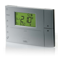
Lc01: Value displayed in the area above the display
Establishes the value displayed in the upper area (see fi g. 6.a).
Value Description
1 Temperature Set point
2 Environmental Room Temperature (Default)
3 Humidity Set point (*)
4 Environmental Room Humidity (*)
(*)Do not set in the absence of the humidity probe.
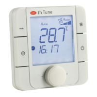
Lc02: Value displayed in the Lower area
Establishes the value displayed in the Lower area (see fi g. 6.b).
Value Description
0 Current time (**)
1 Temperature Set point (Default)
2 Environmental Room Temperature
3 Humidity Set point (*)
4 Environmental Room Humidity(*)
(*) Do not set in the absence of the humidity probe.
(**) If the display of the time is set when the clock hardware is not present the room temperature will be
displayed.
Pc01: Calibration of the environmental probe
Allows to correct the temperature measured by the probe inside the µAD, shown on the display (En05
Parameter) and used for adjustment. The value assigned to this parameter is in fact added to (positi-
ve value) or removed (negative value) from the temperature detected by the probe. For example, if the
temperature displayed is to be decreased by 2.3 degrees, set Pc01=-2.3
.
Range: –9.9 to +9.9 (°C/°F), default: 0.0 (no calibration)
Pr01: Functioning mode
Allows to select the PROCESS or ENVIRONMENT SET POINT functioning mode (see paragraph 5.1).
Value Description
1 PROCESS mode
0 ENVIRONMENT SET POINT mode (Default)
Fr01: Release Firmware
Indicates release of the fi rmware, Fr01 cannot be modifi ed.
6.4 Parameters table
Name Description Paragraph
reference
Min Max Unit of
meas
Default µC
2
µC
2
SE
Ad01 µChiller network address 6.3 1 200 - 1
Co01 Compensation mode 5.13 0 1 - 0
Co02 Compensation in cooling 5.13 1 20
°C/°F
2
Co03 Compensation in heating 5.13 1 20
°C/°F
2
En01 Clock 5.12 0 1 - 1
En02 Buzzer On/Off 6.3 0 2 - 1
En03
Function of key 3
6.3
01 - 0
En04
Manual de-humidifi cation
5.7
01 - 1
En05 Probe inside B01 display 6.3 0 1 - 1
Ht01 Temperature differential 6.3 0,5 10,0
°C/°F
3,0
Hu01 Humidify differential 5.8 5 40 %rH 10
Hu02 De-humidify differential 5.8 5 40 %rH 10
Lc01 Value displayed in upper area 6.3 1 4 - 1
Lc02 Value displayed in lower area 6.3 0 4 - 2
Pc01 Calibration of the environmental probe 6.3 - 9,9 + 9,9
°C/°F
0,0
Pr01 Functioning mode 6.3 0 1 - 0
Fr01 Release Firmware 6.3 - - - -
Tab 6.1
Note:
The last two columns indicate when the parameter is effectively used by the µAD depending on the
µChiller connected.
 Loading...