18
ENG
mpxone +0300086EN rel. 2.2 - 13.11.2023
Installation
2.7 Positioning inside the panel
The position of the controller in the electrical cabinet must be chosen so as to guarantee correct physical separation from the
power components (solenoids, contactors, actuators, inverters, ...) and the connected cables. Proximity to such devices/cables
may create random malfunctions that are not immediately evident. The structure of the panel must allow the correct flow of
cooling air.
2.8 Electrical installation
Caution:
when laying the wiring, “physically” separate the power part from the control part. The proximity of these two sets of wires will,
in most cases, cause problems of induced disturbance or, over time, malfunctions or damage to the components. The ideal
solution is to house these two circuits in two separate cabinets. Sometimes this is not possible, and therefore the power part and
the control part must be installed in two separate areas inside the same panel. For the control signals, it is recommended to use
shielded cables with twisted wires. If the control cables have to cross over the power cables, the intersections must be as near as
possible to 90 degrees, always avoiding running the control cables parallel to the power cables.
Pay attention to the following warnings:
• use cable ends suitable for the corresponding terminals. Loosen each screw and insert the cable ends, then tighten the
screws. When the operation is completed, slightly tug the cables to check they are sufficiently tight;
• separate as much as possible the probe signal, digital input and serial line cables from the cables carrying inductive loads and
power cables to avoid possible electromagnetic disturbance. Never run power cables (including the electrical cables) and
probe signal cables in the same conduits. Do not install the probe cables in the immediate vicinity of power devices (contac-
tors, circuit breakers or similar);
• reduce the path of the probe cables as much as possible, and avoid spiral paths that enclose power devices;
• avoid touching or nearly touching the electronic components fitted on the boards to avoid electrostatic discharges (extreme-
ly damaging) from the operator to the components;
• do not secure the cables to the terminals by pressing the screwdriver with excessive force, to avoid damaging the controller:
maximum tightening torque: 0.22-0.25 N/m.
• For applications subject to considerable vibrations (1.5 mm pk-pk 10/55 Hz), secure the cables connected to the controller
around 3 cm from the connectors using cable ties;
2.9 Serial port connections
For serial connections (FBus and BMS ports), the cables used must be suitable for the RS485 standard (shielded twisted pair, see
the specifications in the following table).
Main device Serial port Lmax (m)
Wire/wire capaci-
tance (pF/m)
resistance on rst
and last device
Max secondary
devices on bus
Baud rate (bit/s)
MPXone FBus 500 <90 120 Ω 9 19200
PC (supervision) BMS 500 <90 120 Ω - 19200
Tab. 1.a
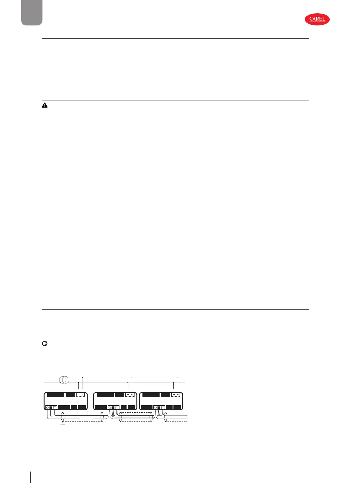
The power supply connections must be in phase between the two controllers (G0 on the main controller and G0 on the sec-
ondary controller connected to the same power supply wire); the serial connection between the two controllers (J5 FBus on the
main and J4 BMS on the secondary) must be made as shown in the following figures (+ with + and - with -).
Notice: Connect a 120 Ω terminating resistor between the Tx/Rx+ and Tx/Rx- terminals on the last controller on the RS485
line.
Main/secondary network
up to 9 secondary for Medium and Advanced models,
u
to 5 secondar
onl
for Basic model
J5
J4
J3
J7
J6
J2
J5
J4
J3
J7
J1
J1
J1
J6
J2
Main Secondary 1 Secondary 2
J5
J4
J3
J7
J6
J2
shield shield shield
G0 GG0 GG0 G
L
N
300086_034_R01
Fig. 2.q
 Loading...