31
ENG
mpxone +0300086EN rel. 2.2 - 13.11.2023
Commissioning
3. In the “Target” tab add a “target”, i.e. the MPXone controller to communicate with.
Fig. 4.e
Notice: the default connection parameters for MPXone are Baudrate=19200, Bits=8, Parity=None, Stop Bits=2, Device Ad-
dress=199
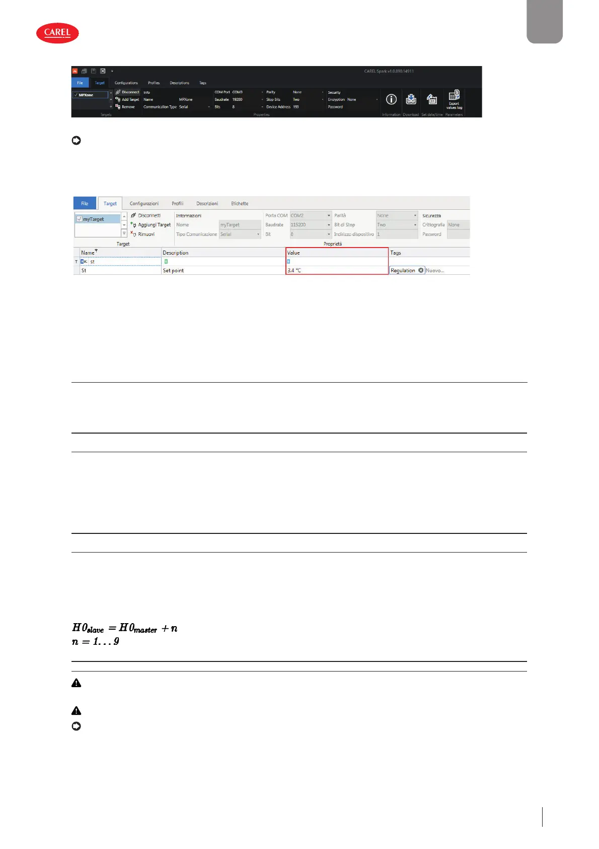
4. Set the serial communication type and modify the connection parameters, as shown in the fi gure. Click “Connect”: the list of
parameters currently loaded on the controller is shown. The “Connect” icon changes to “Disconnect”.
300052_052_R02
Fig. 4.f
5. In the “value” column, enter the desired value for the parameters being modifi ed and confi rm by pressing ENTER.
4.3 Description of the initial con guration parameters
In: Type of unit
Parameter In assigns the function, main or secondary, to the controller.
Code Description Def Min Max UOM User User terminal
In Type of unit
0=Secondary, 1=Main
001- SYES
Sn: Number of secondary devices in the local network
This parameter tells the main controller how many secondary controllers it needs to manage in the local network. If Sn = 0, this
is a stand-alone unit. The maximum number of secondary controllers in a subnet is 9. On secondary controllers, the parameter
must be left at 0.
Code Description Def Min Max UOM User User terminal
Sn Number of secondary devices in the local network
0 = no secondary device
0 0 9 * - S YES
* = up to 9 secondary devices for the Medium and Advanced models, limited to 5 for the Basic model
H0: Serial or main/secondary network address
On a main controller, this represents the address of the controller in the CAREL or Modbus supervisor network.
The address of secondary controllers must comply with the following rule (see the example):
Code Description Def Min Max UOM User User terminal
H0 Serial or main/secondary network address 199 1 247 - S YES
Caution: if multiple main controllers, with their own local networks, are connected to a supervisor network, the address set
for each main controller must consider the number of secondary devices in the previous network.
Caution: when using CAREL protocol (H3=0), the maximum limit of parameter H0 is 207.
Notice: only the main controller needs to be connected to the RS485 serial line (connector J4 BMS), all of the secondary
controllers communicate with the supervisor via the main, connected to the main’s RS485 Fieldbus port (connector J5 FBus).
See “Functional diagrams”.