µRack
Cod. CAREL +03P220431 rel. 2.2 dated 10/02/12
11
Digital inputs
Input Description Type of device connected
ID1
Compressor 1 / fan alarm Generic compressor/fan alarm. Voltage-free contact.
ID2 Compressor 2 /
capacity-control
/ fan alarm
Generic compressor /
Power contactor for capacity control activation
/fan alarm.
Voltage-free contact.
ID3 Compressor 3 /
capacity-control /
fan alarm
Generic compressor /
Power contactor for capacity control activation
/fan alarm.
Voltage-free contact.
ID4 Compressor 4 /
capacity-control
/ fan alarm
Generic compressor /
Power contactor for capacity control activation
/fan alarm.
Voltage-free contact.
ID5 Fan alarm / Multifunction input Generic alarm:
- compressor/fan.
- from general high/low pressure switch.
- fan thermal overload.
- liquid level.
Unit On-Off. Voltage-free contact.
Tab. 3.b
Digital outputs
Input Description Type of device connected
No1-C1 Compressor 1 / fan Power contactor for starting the compressor / fan
No2-C2 Compressor 2 / fan Power contactor for starting the compressor / fan
No3-C3 Compressor 3 / fan Power contactor for starting the compressor / fan
No4-C4 Compressor 4 / fan Power contactor for starting the compressor / fan
No5-C5 Alarm / fan Power contactor for starting the fan / voltage-free contact for signalling unit alarm
Tab. 3.c
Analogue outputs
Outputs Description
Y1
Fans speed controller (PWM)
Tab. 3.d
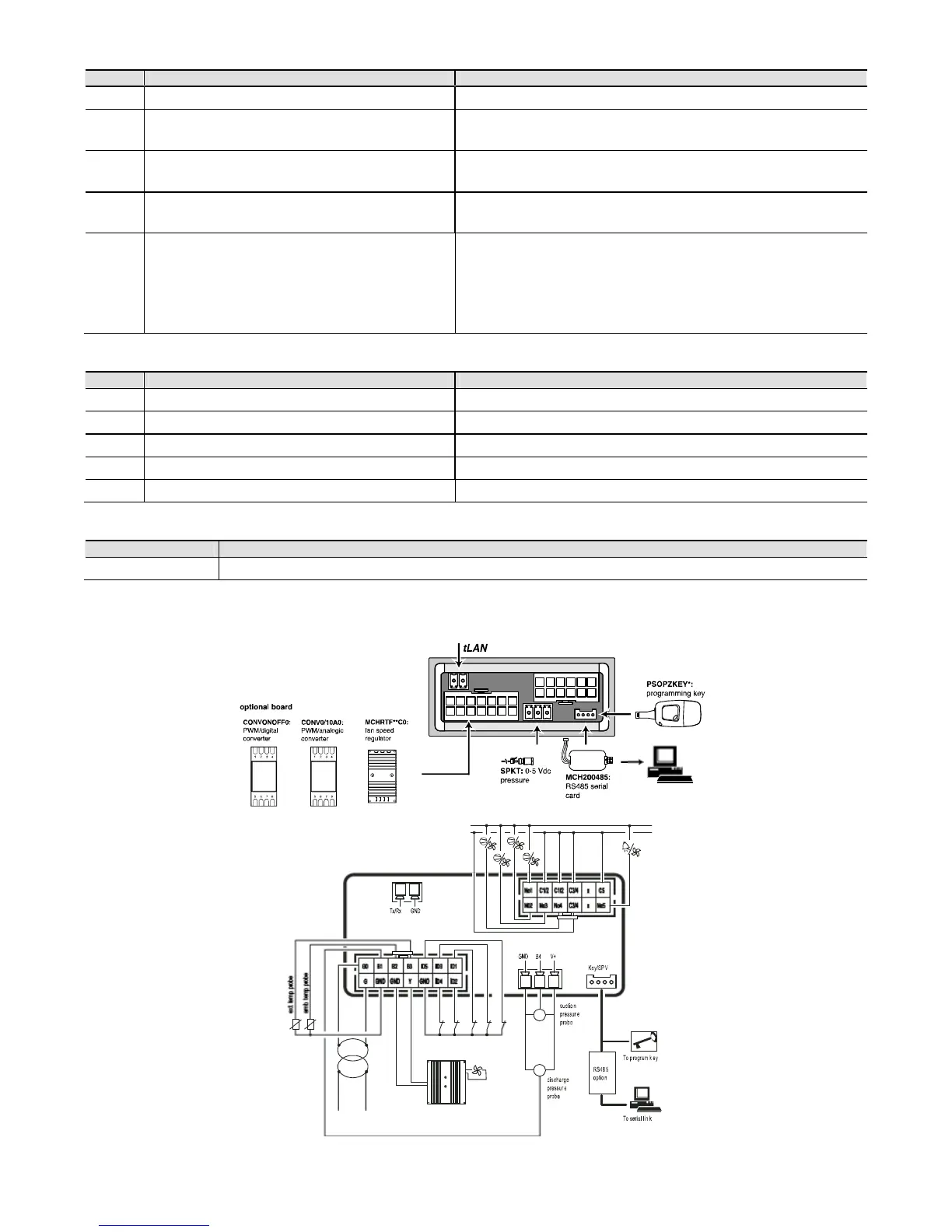
3.3.2 Wiring diagrams:
Panel installation:
Fig. 3.a
ext. temp. probe
amb. temp. probe
alarm 4
alarm 2
alarm 1
alarm 3
multifunctionD.I./alarm
Line
L
N
P
Line
LN
P
24 V
TRADR1W04
PSOPZKEY*
MCH2004850
 Loading...


