µRack
Cod. CAREL +03P220431 rel. 2.2 dated 10/02/12
31
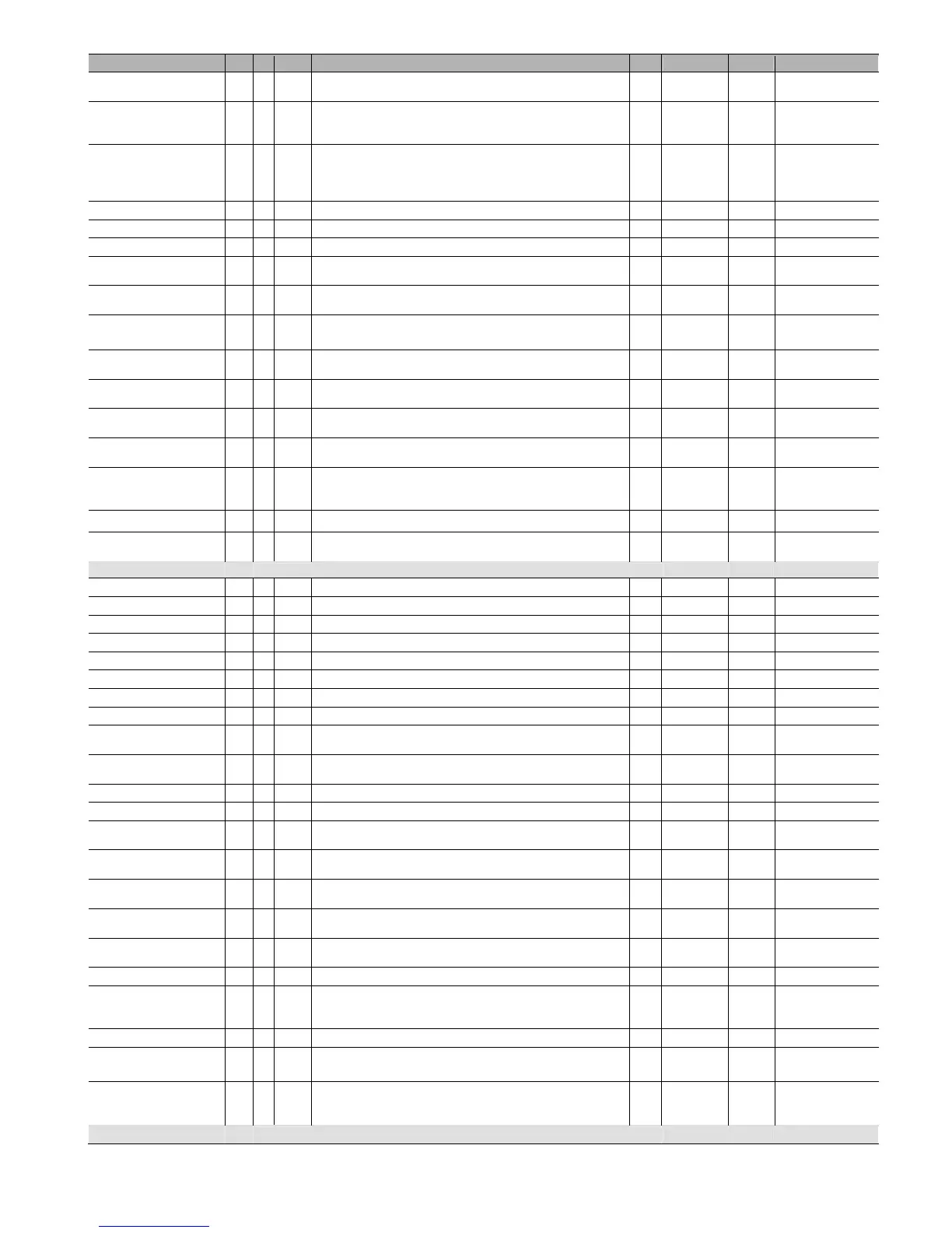
Parameter Type Pos. Display Description UOM Range Default Notes
Fan inverter differential R/W U r19 Fan inverter differential
bar
°C
0 to 20.0
0 to 20.0
3
18
Only if the inverter if
enabled
Fan rotation R/W C r20
Type of fan rotation.
0) NO ROTATION
1) FIFO
0/1 1 For single circuit only
Fan control R/W C r21
Type of fan control:
0) Proportional
1) Proportional + integral
2) Dead band
0 to 2 0 For single circuit only
Integral time (P+I only) R/W C r22 Integral time with P+I control s 0 to 999 600 Only if PI
Time between fan start call R/W C r23 Minimum time between two successive calls to start different fans s 0 to 999 2 xx
Time between fan stop call R/W C r24 Minimum time between two successive calls to stop different fans s 0 to 999 2 xx
Min fan set point R/W C r25 Set the lower limit of the fan set point
bar
°C
0 to r26
-50 to r26
1.0
-31.2
Max fan set point R/W C r26 Set the upper limit of the fan set point
bar
°C
r25 to 40.0
r25 to 150
25.0
55.3
Fan inverter speedup time R/W C r27 Fan inverter speedup time s 0 to 999 2
Only if the inverter is
enabled
Inverter ramp up time R/W I r28 Set the time taken by the inverter to reach full load s 0 to 999 10
Only if the inverter is
enabled
Minimum fan inverter output R/W C r29 Set the minimum operation of the fan inverter % 0 to r30 0
Only if the inverter is
enabled
Maximum fan inverter output R/W C r30 Set the maximum operation of the fan inverter % r29 to 100 100
Only if the inverter is
enabled
Triac impulse duration R/W C r31 Duration of the impulse applied to the triac ms 0 to 10 0
Only if the inverter is
enabled
Enable floating condenser
control
R/W C r32
Enable the floating condenser control
0) NO
1) YES
0 to 1 0
Condensing Delta T R/W C r33 Temperature difference for floating condenser control -40 to 150 10
Compressor management
offset set point
R/W I r34
Compressor bar auxiliary set point offset.
Used when changing the set point from digital input
-99.9 to 99.9 0
Alarm menu
HP suction 1 alarm R/W I A01 Suction probe 1 alarm: high threshold setting bar A03 to /19 9.3
HP suction 1 delay R/W I A02 Suction probe 1 alarm: delay setting s 0 to 999 60
LP suction 1 alarm R/W I A03 Suction probe 1 alarm: low threshold setting bar /17 to A01 0
LP suction 1 delay R/W I A04 Suction probe alarm: delay setting s 0 to 999 60
HP suction 2 alarm R/W I A05 Suction probe 2 alarm: high threshold setting bar A07… /20 20 For two circuits only
HP suction 2 delay R/W I A06 Suction probe 2 alarm: delay setting s 0 to 999 60
LP suction 2 alarm R/W I A07 Suction probe 2 alarm: low threshold setting bar /18 to A05 0 For two circuits only
LP suction 2 delay R/W I A08 Suction probe alarm: delay setting s 0 to 999 60
HP discharge alarm R/W I A09 Discharge probe alarm: high threshold setting
bar
°C
A10 to /20
A10 to 150
20.0
45.8
LP discharge alarm R/W I A10 Discharge probe alarm: low threshold setting
bar
°C
/18 to A09
-50 to A09
0
-50
Discharge delay R/W I A11 Discharge probe alarm: delay setting s 0 to 999 60
Compressor thermal delay R/W I A12 Compressor thermal overload alarm: delay setting s 0 to 999 0
HP prevention
Prevent time 1
R/W I A13 Time in which start calls are ignored after prevent HP m 0 to 99 5
Only if the prevent is
enabled
HP prevention
Prevent time 2
R/W I A14
If two prevent alarms occur within this time, an excessive prevent frequency
alarm is generated
m 0 to 999 6
Only if the prevent is
enabled
HP prevention
Prevent time 3
R/W I A15
If no prevent alarms occur in this period, the high prevent frequency alarm is
automatically reset
m 0 to 99 30
Only if the prevent is
enabled
High temp. probe threshold:
B2
R/W I A16 High temperature threshold, probe B2 °C -40 to 150 100
High temp. probe threshold:
B3
R/W I A17 High temperature threshold, probe B3 °C -40 to 150 100
Delay liquid level alarm R/W I A18 Set the liquid level alarm delay from multifunction input m 0 to 500 60
Reset ALARMS R/W U A19
Reset the alarms with manual reset
0) NO RESET
1) RESET
0/1 0
Alarm signal delay R/W I A20 Set alarm signal delay s 0 to 999 1
Exchange auto->man LP 3
alarms
R/W I A21
On the 3rd activation, within the set time, the low pressure alarm from
pressure switch changes from automatic to manual reset.
m 0 to 999 10
OFF due to probe
disconnected
R/W I A22
Enable unit OFF due to probe disconnected/alarm
0) NO
1) YES
0/1 0
Maintenance menu
 Loading...


