pCO Sistema
Code: +030220336 - rel. 1.5 - 22/12/10
30
3.1.10
3.1.103.1.10
3.1.10 Maximum distance
Maximum distanceMaximum distance
Maximum distance
The maximum distances between the pCO and the user terminal are shown in the following table.
type of cable
type of cable type of cable
type of cable
power supply distance
power supply distancepower supply distance
power supply distance
power supply
power supplypower supply
power supply
telephone 50 m taken from pCO (150 mA)
AWG24 shielded cable 200 m taken from pCO (150 mA)
AWG20/22 shielded cable 500 m separate power supply via TCONN6J000
Tab. 3.d
Tab. 3.dTab. 3.d
Tab. 3.d
The maximum distance between two pCO controllers with AWG20/22 shielded twisted pair cables is 500 m. When developing the network, use a bus layout with
branches that do not exceed 5 m. For further information, see Chapter 5.
User terminal/interface connecti
User terminal/interface connectiUser terminal/interface connecti
User terminal/interface connection cables
on cableson cables
on cables
length (m)
length (m)length (m)
length (m)
type
typetype
type
code
code code
code
0.8 telephone connectors S90CONN002
1.5 telephone connectors S90CONN000
3 telephone connectors S90CONN001
6 telephone connectors S90CONN003
Tab. 3.e
Tab. 3.eTab. 3.e
Tab. 3.e
3.1.11
3.1.113.1.11
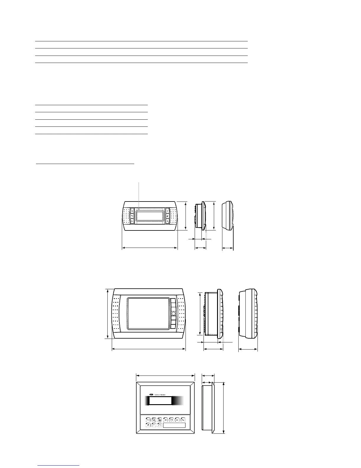
3.1.11 Dimensioni display (in mm)
Dimensioni display (in mm)Dimensioni display (in mm)
Dimensioni display (in mm)
Remote terminal installation
Remote terminal installationRemote terminal installation
Remote terminal installation
acce
acceacce
accessories for electrical connections
ssories for electrical connectionsssories for electrical connections
ssories for electrical connections
code
code code
code
board for remote terminal installation TCONN6J000
Dimensions: PGD0/1
Dimensions: PGD0/1Dimensions: PGD0/1
Dimensions: PGD0/1
156
30
31
18
67
82
Built-in
assembly
Wall
mounting
pGD1* display
dimensions
Fig. 3.g
Fig. 3.gFig. 3.g
Fig. 3.g
Dimensions: PGD2/3
Dimensions: PGD2/3Dimensions: PGD2/3
Dimensions: PGD2/3
221
58
56,3
40,5
 Loading...


