pCO Sistema
Code: +030220336 - rel. 1.5 - 22/12/10
29
3.1.7
3.1.73.1.7
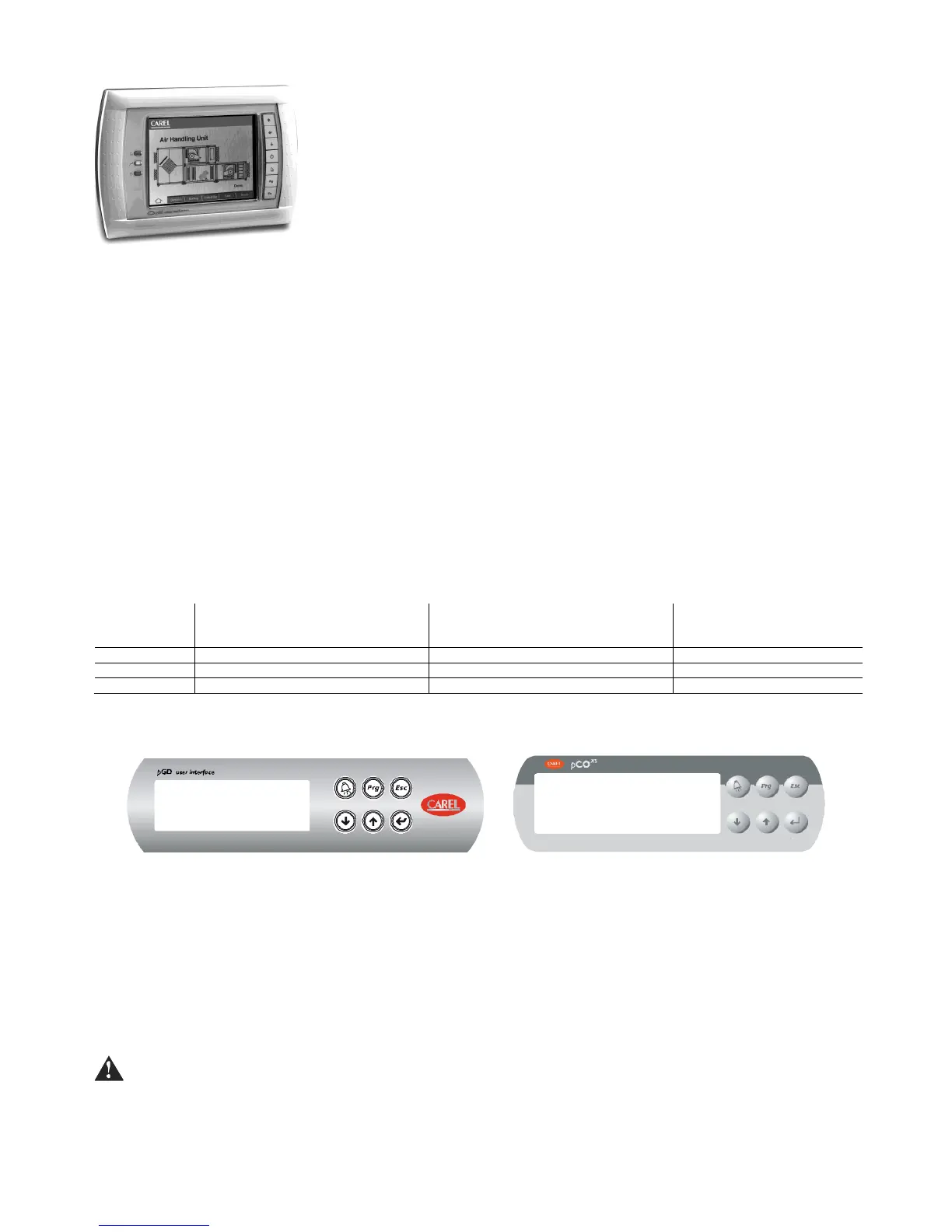
3.1.7 pGD2/3
pGD2/3 pGD2/3
pGD2/3 -
--
-
pCO graphic display
pCO graphic displaypCO graphic display
pCO graphic display
Versions:
Versions:Versions:
Versions:
- Panel installation (code PGD*00*F0*)
- Wall-mounting (code PGD*00*W0*)
pGD
pGDpGD
pGD
2
22
2
LCD colours monochromatic (blue/white)
resolution 320x240 pixels
backlighting by LED.
pGD
pGDpGD
pGD
3
33
3
LCD colours 256 colours
resolution 320x240 pixel
backlighting by CCFL fluorescent light.
protocols supported: pLAN protocol, “Local terminal” protocol (text mode only)
LEDs 2 controlled by application
Configuration:
Configuration:Configuration:
Configuration:
pGD 2/3 is configured in the factory for the most common user requirements, nonetheless some settings can be
changed to adapt it to specific needs.
Updating the firmware:
Updating the firmware:Updating the firmware:
Updating the firmware:
The firmware of the pGD2/3 terminal can be updated when new versions become available, using the “Display
Firmware Update” function accessible from the “General Options” menu.
Power supply:
Power supply:Power supply:
Power supply:
power supply: 24 Vac ±15%, 50/60 Hz or 30 Vdc ± 25%
rated power: 10 W
Use a class 2 safety transformer with a minimum rating of 15 VA.
3.1.8
3.1.83.1.8
3.1.8 Built
BuiltBuilt
Built-
--
-in display
in displayin display
in display
The pCO
XS
and pCO
3
feature versions with a Built-In terminal: the display and keypad are incorporated directly into the plastic case. It is availabele for the pCO
3
specifically, a graphic LCD and in all versions ( SMALL, MEDIUM, LARGE, EXTRALARGE NO, EXTRALARGE NC). The built-in terminal on the pCO
XS
does not have a
graphic display.
Features
FeaturesFeatures
Features
PCO3000*S0, PCO3000*M0, PCO3000*L0,
PCO3000*Z0, PCO3000*C0
* = B, D, H
PCO3000*S0, PCO3000*M0, PCO3000*L0,
PCO3000*Z0, PCO3000*C0
* = E, F, I
Tab. 3.c
Tab. 3.cTab. 3.c
Tab. 3.c
These versions with integrated LCD and keypad also support connection to all the pCO series terminals (the two displays, built-in and standard, work at the same time,
displaying the same information).
built-in terminal
Fig. 3.f
Fig. 3.fFig. 3.f
Fig. 3.f
The display contrast can be adjusted on this version of the terminal.
To do this :
1. press the Enter and Esc buttons together;
2. holding the two buttons, use UP or Down to adjust the contrast as required (increase or decrease respectively).
3.1.9
3.1.93.1.9
3.1.9 Connecting the user terminal to the pCO
Connecting the user terminal to the pCOConnecting the user terminal to the pCO
Connecting the user terminal to the pCO
The typical connection between the pGD terminal and the pCO is made using a 6-wire telephone cable supplied by Carel (code S90CONN00*). To make the
connection simply plug the cable into the 6-pin connector on the pCO (J10 for pCO3 and pCO1, J5 for pCO
XS
, J19 pCOC), so that it clicks into place. To remove the
connector, lightly press the plastic tab and pull out the cable. The telephone connector provides both the data link and the power supply to the terminal, and is the
simplest connection method; in more complex configurations, where more than one terminal is connected to the pCO or to cover lengths in excess of 50 m, a twisted-
pair cable with shield is required (see the diagrams in chap. 5).
Shielded cable must also be used if the pCO is installed in domestic or similar environments, and consequently subject to the requirements of IEC EN 55014-1
of 04/98) – (see paragraph 5.7).
When developing a pLAN network of pCO controllers and terminals, always remember that a pCO can only supply power to one pGD0/1 or old pCOT/I terminal. If it is
necessary to manage more than one terminal or the pGD2/3 versions, an independent power supply is required (see the diagrams in chap. 5). The DC voltage at
Vterm (J24 for pCO
3
, J9 for pCO
1
) can supply an ARIA or PLD terminal with a maximum power input of 2 W. The pCO can operate perfectly without the terminal
connected.
Fig. 3.e
Fig. 3.eFig. 3.e
Fig. 3.e
 Loading...


