pCO Sistema
Code: +030220336 - rel. 1.5 - 22/12/10
51
LonWorks®
LonWorks® LonWorks®
LonWorks® serial board
serial boardserial board
serial board:
: :
: PCO10000F0
PCO10000F0PCO10000F0
PCO10000F0
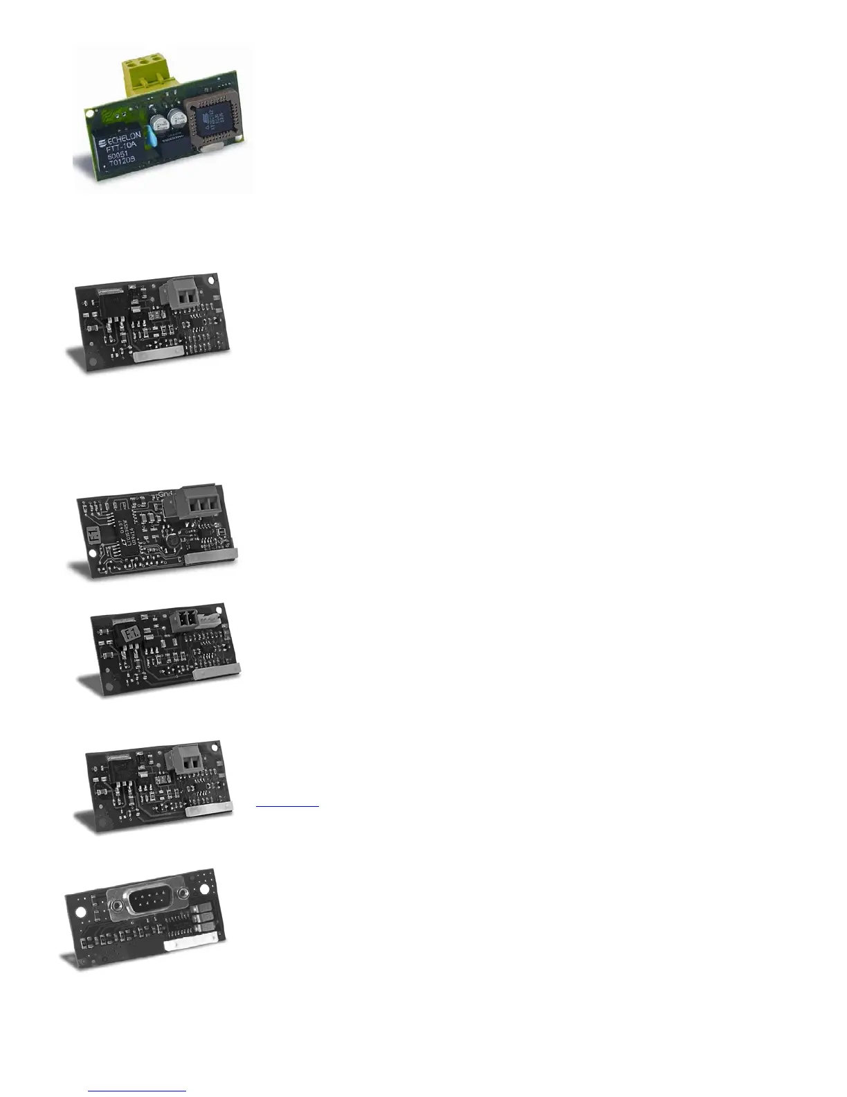
The PCO10000F0 and PCO10000R0 optional boards for the pCO electronic controllers are used to interface these with a
LonWorks network®.
Warning:
Warning:Warning:
Warning: in order to be operational, the interface board must be programmed based on the application installed on the
pCO.
Information on the procedure for programming the board is provided in the manual code +030221960.
The program is resident in flash memory fitted on a socket, and can be programmed directly via the LonWorks®
network, using the network installation and maintenance tools such as LonMaker™.
The boards differ based on the type of LonWorks® network interface and the type of electronic controller it can be fitted
on:
• PCO*0000F0 - interface to FTT-10A 78 kbs (TP/FT-10);
• PCO*0000R0 - interface to RS485 39 kbs (TP/485-39).
The baud rate of the pCO must be set to 4800, while the pCO address is not significant, as this is automatically recognised by the
board. An option already programmed with the standard chiller profile is also available: code PCO10001F0. For the
technical specifications and the meanings of the connections (pins), as well as details on the procedure for fitting the
board, follow the instructions shown on the instruction sheet provided in the packaging (code +050004040).
TREND board
TREND boardTREND board
TREND board:
: :
: PCO100CLP0
PCO100CLP0PCO100CLP0
PCO100CLP0
This is used for communication with the TREND interface, a building automation system that is very widespread in
English-speaking countries.
6.2.2
6.2.26.2.2
6.2.2 Serial boards for connection to a “field bus” network
Serial boards for connection to a “field bus” networkSerial boards for connection to a “field bus” network
Serial boards for connection to a “field bus” network
The optional Field bus boards offer a serial interface that allows the pCO
3
and pCO
1
to communicate with other devices over various standards. In fact, the tLAN, MP
bus and RS485 options interface the pCO to a network of devices including actuators, probes, expansions and terminals.
Electrically insulated RS485 serial board:
Electrically insulated RS485 serial board: Electrically insulated RS485 serial board:
Electrically insulated RS485 serial board: PCO100FD10
PCO100FD10PCO100FD10
PCO100FD10
The PCO100FD10 option is used to connect the pCO3 and pCO1, via an electrically insulated interface, to an RS485
network, using the connector with plug-in terminals on the board. The controller consequently acts as the MASTER (i.e.
supervisor), and therefore other pCO controllers or SLAVE devices can also be connected. The meaning of the pins on the
connector are denoted by the screen printing on the board. A maximum of 207 connectable devices using this type of
connection. If the optional board occupies the last position on the supervisor serial line and the line is longer than 100m, the
line must be terminated by connecting a 120Ω - 1/4 W resistor to the terminal pins.
If the function set is SLAVE, on the other hand, only one pCO with this optional board can be connected to the network.
tLAN and PST board:
tLAN and PST board: tLAN and PST board:
tLAN and PST board: PCO100TLN0
PCO100TLN0PCO100TLN0
PCO100TLN0
The PCO100TLN0 option is used to connect the pCO
1
to a tLAN network using two separate connectors.
The first connector is used to connect the pCO
3
and pCO
1
to a tLAN network. Using this connection and a suitably-configured
application in TLAN MASTER mode, the pCO
1
can interact with the pCO I/O expansion (tLAN version - PCOE00TLN0) or with
other pCO controllers fitted with a tLAN connection, configured in tLAN SLAVE mode.
A maximum of 5 connectable devices using this type of connection.
The second connector, on the other hand, is used to connect a PNT or PST terminal. Using this connection and a suitably-
configured application, the pCO
3
and pCO
1
can interact with a PNT terminal. Both connections require a shielded cable with a
maximum length of 10 m.
Important:
Important:Important:
Important: the two connectors cannot be used at the same time.
MP
MPMP
MP-
--
-Bus board:
Bus board: Bus board:
Bus board: PCO100MPB0
PCO100MPB0PCO100MPB0
PCO100MPB0
The PCO100MPB0 option is used to connect the pCO
3
and pCO
1
to an MP-Bus network made up of I/O devices according to
the Belimo standard. Up to 8 actuators can be connected at the same time, over a maximum distance of 30 m. For the
connection of a temperature sensor, active or passive, or a digital contact, see the specific Belimo documents
(www.belimo.ch).
As regards the procedure for setting the network addresses, these are described in the specific manuals on the individual
applications. For the technical specifications and the meanings of the connections (pins), as well as details on the procedure
for fitting the board, follow the instructions shown on the instruction sheet provided in the packaging (code +050003270).
RS232 serial board for modem management:
RS232 serial board for modem management: RS232 serial board for modem management:
RS232 serial board for modem management: PCOS00FD20
PCOS00FD20PCOS00FD20
PCOS00FD20
The PCOS00FD20 board is an option for the pCO1/pCO3 electronic controllers to interface these directly with a standard
HAYES modem. The board manages the “request to send” (RTS) in parallel with the “data terminal ready” (DTR).
For the technical specifications and the meanings of the connections (pins), as well as details on the procedure for fitting the
board, follow the instructions shown on the instruction sheet provided in the packaging (code +050003295)
 Loading...


