pCO Sistema
Code: +030220336 - rel. 1.5 - 22/12/10
52
CANbus
CANbusCANbus
CANbus
serial board
serial boardserial board
serial board: PCOS00HBF0
: PCOS00HBF0: PCOS00HBF0
: PCOS00HBF0
These devices allow the pCO controllers to be connected to CANbus networks, and more precisely, to the e-drofan
controllers for fan coils, exploiting the potential of the e-dronic system. This ensures simpler management of the
installation, optimising comfort, synergies between the controllers and running costs. For the technical specifications and
the meanings of the connections (pins), as well as details on the procedure for fitting the board, follow the instructions
shown on the instruction sheet provided in the packaging (code +050000162).
6.2.3
6.2.36.2.3
6.2.3 Other types of optional boards
Other types of optional boardsOther types of optional boards
Other types of optional boards
Memory expansion PCO100CEF0
Memory expansion PCO100CEF0Memory expansion PCO100CEF0
Memory expansion PCO100CEF0
If the flash memory is not sufficient for the application program or the logs, the capacity of the pCO
1
can be expanded by fitting
an expansion board. This option also includes the clock board and 32 KB of E2PROM memory. Consequently, remove the
PCO100CLK0 if the PCO100CEF0 is used. For the technical specifications and details on how to insert the expansion board,
carefully follow the instructions shown on the instruction sheet provided in the packaging. For information on the connections
and the sequence of the operations, see the instruction sheet (code +050003245).
Clock boar
Clock boarClock boar
Clock board PCO100CLK0
d PCO100CLK0d PCO100CLK0
d PCO100CLK0
For the pCO
1
and pCO
XS
, the PCO100CLK0 board option is used to manage the time and date, as well as providing and extra 52
bytes of RAM with battery backup. Do not fit this option on a pCO
1
that has been installed with the PCO100CEF0.
For the technical specifications and the meanings of the connections (pins), as well as details on how to insert the expansion
board, follow the instructions shown on the instruction sheet provided in the packaging. For information on the connections and
the sequence of the operations, see the instruction sheet (code +050003230).
IMPORTANT WARNINGS
IMPORTANT WARNINGSIMPORTANT WARNINGS
IMPORTANT WARNINGS: operator safety and precautions to be observed when handling the board/boards.
To safeguard operators and the boards, disconnect power before performing any operations.
Electrical damage may occur to the electronic components as a result of electrostatic discharges from the operator. Suitable
precautions must be therefore be taken when handling these components. Specifically:
• before using any electronic component or board, touch an earthed object (simply not touching the board does not
prevent discharges, as static electricity can produce a 10000V spike, which can form an arc of about 1cm);
• all components must be kept inside their original package as long as possible. If necessary, take the board from its
package and place it into an antistatic bag, without touching the back of the board;
• absolutely avoid using non-antistatic plastic bags, polystyrene or sponge, and avoid passing the board directly to other
operators (to prevent electrostatic induction and consequent discharges).
6.2.4
6.2.46.2.4
6.2.4 External modules and interfaces
External modules and interfacesExternal modules and interfaces
External modules and interfaces
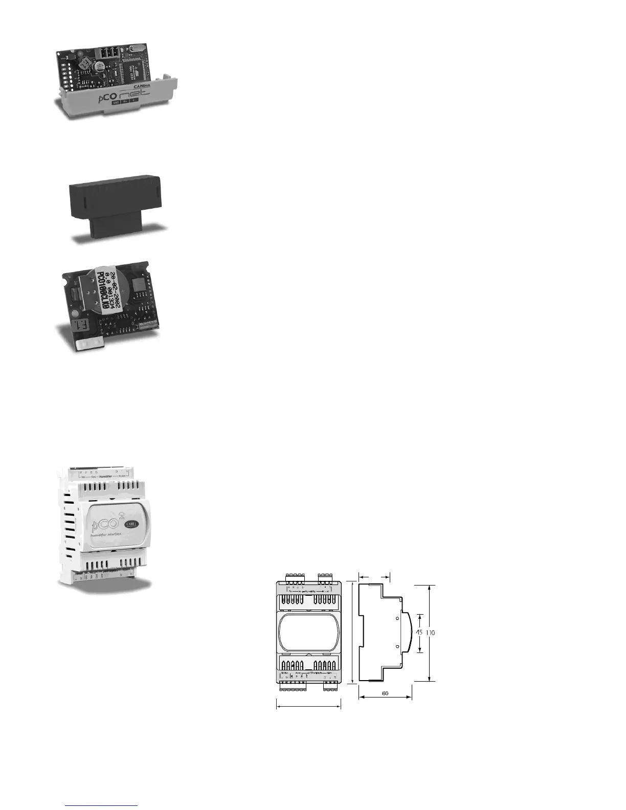
Interface for the OEM series humidifiers (PCOUMI2000)
Interface for the OEM series humidifiers (PCOUMI2000)Interface for the OEM series humidifiers (PCOUMI2000)
Interface for the OEM series humidifiers (PCOUMI2000)
The PCOUMI2000 module is an interface for the pCO electronic controllers. This allows the control of the fundamental parameters
of the OEM humidifiers manufactured by CAREL (level and conductivity of the water in the cylinder, TAM sensor for current input)
directly from the pCO electronic microprocessor controller. The values measured by the sensors are converted into signals that can
be read by the inputs on the pCO (for more information refer to the user manual for the application program).
The PCOUMI2000 interface differs from the PCOUMID000 interface due to:
- greater precision and immunity to disturbance both as regards the conductivity reading and the level sensor;
- the “high water level” signal can be managed either as a digital or analogue output.
Consequently, the controller can be connected to both the PCOUMID000 and the PCOUMI2000 board, with the only difference
being the setting of the corresponding parameter, so as to tell the software to use the correct conductivity curve.
44
Fig. 6.b
Fig. 6.bFig. 6.b
Fig. 6.b
For the technical specifications and the meanings of the connections (pins), as well as details on the procedure for fitting the board, follow the instructions shown on
the instruction sheet provided in the packaging (code +050003210).
 Loading...


