pCO Sistema
Code: +030220336 - rel. 1.5 - 22/12/10
53
DC/DC module (PCO20DCDC0)
DC/DC module (PCO20DCDC0)DC/DC module (PCO20DCDC0)
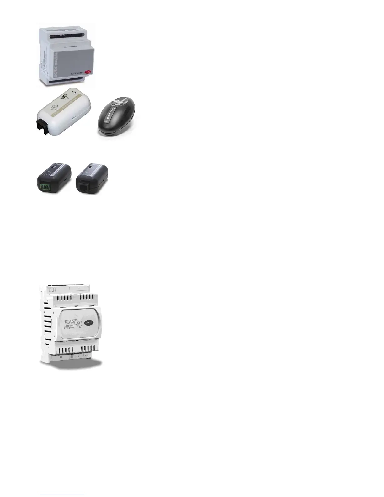
DC/DC module (PCO20DCDC0)
The PCO20DCDC0 power supply module is an option for the pCO electronic controllers.
It stabilises the DC output voltage at 24±1 Vdc/0.7 A (pCO controller side) for input voltages (power source) from 21 to 58 Vdc (for
example, from 48 Vdc storage batteries, typically used in telephone applications).
The maximum power delivered is 17 W, which can supply any pCO electronic controller. The input and output of the power supply
module feature functional galvanic isolation.
For the technical specifications and the meanings of the connections (pins), as well as details on the procedure for fitting the board,
follow the instructions shown on the instruction sheet provided in the packaging (code +050004020).
SMART KEY (PCOS00AKY0 and PCOS00AKC0)
SMART KEY (PCOS00AKY0 and PCOS00AKC0) SMART KEY (PCOS00AKY0 and PCOS00AKC0)
SMART KEY (PCOS00AKY0 and PCOS00AKC0)
The PCOS00AKY0 key is an electronic device used to program and manage the pCO sistema family controllers.
PCOS00AKY0 simplifies the transfer of data between the installed controllers and a personal computer, and
features ample flash memory for storing software applications, Bios and variable logs. The key is connected to the
pCO directly via the telephone connector using the cable supplied, while to transfer data to/from a personal
computer, the USB adapter code PCOS00AKC0 is required (not optically-isolated converter, for the Smart Key
only). The power supply can come either from the USB port on the PC or from the controller, therefore no
external power supply is required. For the technical specifications and the meanings of the connections (pins as
well as details on the procedure for fitting the board, follow the instructions shown on the instruction sheet
provided in the packaging (code +050003420).
USB/RS485 converter (CVSTDUMOR0/CVSTDUTLF0)
USB/RS485 converter (CVSTDUMOR0/CVSTDUTLF0)USB/RS485 converter (CVSTDUMOR0/CVSTDUTLF0)
USB/RS485 converter (CVSTDUMOR0/CVSTDUTLF0)
The USB-RS485 converter is an electronic device that is used to interface a RS485 network with a personal computer
via the USB port, to be used with WINLOAD. The converter is available in two versions: CVSTDUTLF0, fitted with a six-
pin telephone connector, and CVSTDUMOR0, fitted with a three-pin terminal block. These are optically-isolated and
cannot be used with the Smart Key. For the technical specifications and the meanings of the connections (pins), as
well as details on the procedure for fitting the board, follow the instructions shown on the instruction sheet provided
in the packaging (code +050000590).
pCO I/O expansion boards
pCO I/O expansion boardspCO I/O expansion boards
pCO I/O expansion boards
The “PCOE000TLN0 and PCOE0004850” expansion boards are electronic devices that are part of the pCO sistema family and have been designed to increase the
number of I/Os available for the pCO controllers. A maximum of 5 expansion boards can be connected to each pCO controller.
Versions available:
Versions available:Versions available:
Versions available:
• PCOE00TLN0 tLAN version (CAREL proprietary protocol);
• PCOE004850 RS485 version (CAREL 3.0 supervisor protocol).
For the technical specifications and the meanings of the connections (pins), as well as details on the procedure for fitting the board, follow the instructions shown on
the instruction sheet provided in the packaging (code +050003265).
Driver
Driver Driver
Driver for electronic expansion valves (EVD*400)
for electronic expansion valves (EVD*400)for electronic expansion valves (EVD*400)
for electronic expansion valves (EVD*400)
The EVD0000400 module for electronic expansion valves with two-pole stepper motor is a controller that manages the
expansion of the refrigerant in a refrigerant circuit. This function is achieved by optimising the opening of the valve using a PID
algorithm and some special auxiliary control routines. The driver has a tLAN interface for connection to a Master unit, an RS485
adapter (featured in models *410, *411, *420 and *421) that allows connection to units with the supervisor protocol, from
4800 to 19200 baud, or with the pLAN protocol. The driver automatically recognises the protocol and the baud rate.
Alternatively, the driver can operate in stand-alone mode.
As well as the serial connection, in any configuration described above, the driver can be accessed for configuration or
monitoring via an auxiliary “service” serial port at 4800 baud with supervisor/tLAN protocol and network address = 1 (fixed).
The USB converter CVSTDUTTL0 is required to use the “service” serial port. This connection is for temporary use. If using the
“service” serial port or the supervisor protocol on the main serial port, the EVD4UI program is available; this has a user-friendly
graphic interface and is available on the KSA site.
Phase control module
Phase control modulePhase control module
Phase control module
The controller works with two-pole stepper motors. It operates with a theoretical sinusoidal waveform, in micro-steps and with
speeds from 5 to 1000 steps; the current and the control speed effectively achievable depend on the resistance and the inductance
of the motor windings used. If the driver is connected to a pCO, it receives all the individual operating parameters for the motor
from the pCO controller. The controller can manage motors with maximum positions of up to 32000 steps.
For connection use 4-wire shielded cables, AWG18/22, max. length 9.5 m.
The shield should be connected to the closest possible earth point in the panel. For the technical specifications and the meanings
of the connections (pins), as well as details on the procedure for fitting the board, follow the instructions shown on the instruction
sheet provided in the packaging (code +050003875).
 Loading...


